MSD 101: Modeling and simulation
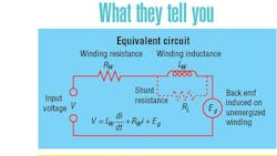
Motor models can be a great help when it comes to designing the control portion of a motion system. The relatively simple construction of motors — copper coils, iron cores, and magnets — readily reduces to an equivalent electrical circuit. In this way, ac, dc, brushed, brushless, and reluctance motors can be represented as a combination of resistors, inductors, and voltage sources. These models can be solved to generate speed-torque curves and to quantify the effect of voltage and current on motor operation. The following analysis applies to brushless dc and permanent magnet type motors.
Questions & Answers
Q. What about running a motor in reverse?
A. The models here show only the first quadrant of the speed-torque curve. Other quadrants express operating modes such as reverse and “regen,” where an idling motor generates current as it spins down.
Q. Are linear speed-torque curves better?
A. Depends what you need to do. A motor with linear speed-torque is usually easier to control, especially if you plan on fourquadrant operation. Likewise, if your goal is servo control.
Q. What can a motor model tell me about proper sizing and control?
A. A lot. From a regulated speed curve, you can determine if the motor has enough speed and torque, and how much voltage and current it will need.
