Couplings offer precise positioning, damping too
Today’s linear drives — as used in CNC machines, laser cutting machines, milling machines, and robots — demand both positioning accuracy and smooth, vibration-free operation. This usually requires, among other things, fine tuning the drive. In designing a slide axis, for example, a design engineer carefully selects components such as motor, ball screw, spindle, table, and bearings. This involves evaluating each component to ensure that the total drive system has adequate torsional stiffness to meet precise positioning requirements.
In a typical case, a designer might select a helical or bellows type coupling because it has 5 or 6 times the torsional stiffness of a jaw coupling. But, as the following calculations show, the coupling stiffness often has far less effect on the total system stiffness than the “5 or 6” implies.
The drive system may also need to dampen vibration, which can cause incorrect positioning and poor finish on machined parts. In such cases, a relatively stiff jaw coupling, which uses an elastomeric element to dampen vibration, may offer the best balance between stiffness and damping for your application.
One such jaw coupling is assembled with an interference fit between hubs and elastomeric element, Figure 1. The tight fit preloads the elastomeric element to reduce backlash, which helps to minimize positioning error.
Calculating drive stiffness
The following example compares the torsional stiffness of a drive system with two types of couplings: a torsionally stiff metal bellows coupling, and a jaw coupling of comparable size (32-mm ID) with less torsional stiffness. A machine tool drive consists of a servomotor coupled to a spindle assembly, which contains a fixed bearing, ball spindle, spindle nut, and movable bearing. Drive parameters are:
Torsional stiffness of servomotor,
Cm = 90,000 Nm/rad Torsional stiffness of jaw coupling,
Cj = 21,000 Nm/rad Torsional stiffness of bellows coupling,
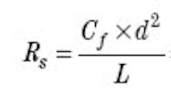
Cb = 116,000 Nm/rad Spindle key height, h = 10 mm Root diameter of ball spindle, d = 28.5 mm Length of spindle, L = 800 mm Axial stiffness of fixed bearing,
Rbrg = 750 N/μm Axial stiffness of spindle nut,
Rn = 1,060 N/μm Speed reduction ratio, i = 1 Stiffness constant for linear drives,
Cf = 165
Step 1. Find the axial stiffness of the drive system, then convert to torsional stiffness. The axial stiffness of the spindle is:
For most applications, design engineers would sacrifice 1 or 2% torsional stiffness to eliminate the vibration often found in torsionally stiff drives. This can be accomplished by using a relatively stiff jaw coupling, as described in this example, that also dampens vibration.
Linear slide application
A manufacturer of hydraulic, pneumatic, and electrically powered automation devices, PHD Inc. of Fort Wayne, Ind., has a series of tangential belt slides that are used mainly for linear multiple positioning applications. Depending on the application, these devices are normally driven by either servo or step motors.
Historically, the belt slide, Figure 2, has always used a one-piece helical coupling between the drive motor and belt pulley. However, because of a change in servo controllers and associated coupling resonance problems, the company had to find a different type of coupling. The belt slide allowed only a limited amount of space for the new coupling. This alone eliminated several coupling types from consideration.
PHD finally chose the Rotex GS series coupling, which offered features not available with helical couplings. The main benefit of this jaw-type coupling was a change in damping characteristics, which was enough to move the system’s natural frequency away from the resonant frequency that plagued the drive with the previous coupling. PHD engineers cite other advantages including backlash-free motion, a double setscrew fastening arrangement to eliminate shaft slippage, and more durability in high-cycle applications. Additionally, the elastomeric insert in this type of coupling can be supplied in one of several different hardnesses (durometers) to accommodate a range of angular and axial displacements.
John G. Dick is the senior application engineer, North American Operations, KTR Corp., Michigan City, Ind. Johannes Deister is a design engineer, KTR Kutplungstechnik GMBH (Rheine, Germany).
