Calculating the effect of rotating cylinders on servo-system acceleration
A component’s moment of inertia is its resistance to rotational acceleration.
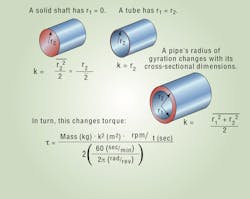
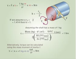
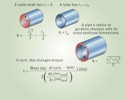
Of course, that value partly depends on mass. But one more factor affects how much force is needed to get a component spinning: geometry. Also known as a radius of gyration, k expresses this part of inertia (normally determined from known component dimensions) in units of length. From there, calculate rotational inertia I = mass x k2.
Q: When is it necessary to study the inertial characteristics of cylinders?
A: They’re relevant whenever an apparatus must accelerate and response is crucial. They predict the performance of shafts and other spinning components — motors, clutches, and couplings. Inertial characteristics also affect speed and load regulation capabilities. One caveat: because the equations are good for modeling only one aspect of drive shafts, other mechanical drive component characteristics (such as backlash and stiffness) are also required.
Q: How are the results useful to designing open and closed control loops?
A: They help determine the potential response capabilities or limitations of open and closed control loops — such as torque, speed, tension, position, and level. More specifically, it’s critical to know rotational inertia for servo positioning, robotics, and cut-tolength applications that often require near-step, instant accelerations. (In these applications, it’s not uncommon that these drives be limited mechanically or electrically.)
Acceleration and deceleration criteria can vary significantly, even within a process. On paper-making machines, for example, forming, dewatering, pressing, and drying limit in-process rates of acceleration to 1.5 to 2.5 ft/min./sec. However, on the same system a paper winder with multiple set cycle times (and needing to keep ahead linear paper production) might regularly accelerate at 150 ft/min./sec. In these cases, inertial results help qualify the sizing of each mechanical and electrical drive component.
Q: What if a designer can tweak component dimensions and weight?
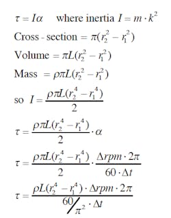
A: If a designer has the freedom (or the need) to adjust, for example, the shaft material or motor weight during the design process, then keeping density a variable makes sense. A more general form of the torque equation can be used. Note how the common terms
of mass and radius of gyration combine in the equation below.
Tips provided by Pete Werner, senior principal engineer at Rockwell Automation, Drive Systems Engineering. For more information call (800) 669-6119 or visit www.automation.rockwell.com/drivesystems.
About the Author
Elisabeth Eitel
Elisabeth Eitel was a Senior Editor at Machine Design magazine until 2014. She has a B.S. in Mechanical Engineering from Fenn College at Cleveland State University.


