Review of quadrature-encoder signals

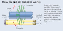
The sensing mechanism in an incremental optical rotary encoder consists primarily of a light source, code wheel, and optical detector. As the code wheel turns, a ring of alternating opaque and transparent regions shutters the light between the source and detector, creating a series of pulses.
Questions & Answers
Q: What is the resolution of a 1,000-line encoder?
A: The base resolution is 0.360°. Resolution obtainable by quadrature signaling is four times better, or 0.090°. Electronic interpolation – mathematically predicting position between data points – can achieve even higher resolutions.
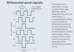
Q: How is direction encoded in quadrature signals?
A: In the typical quadrature relationship, counterclockwise (CCW) rotation causes the signal designated as “A” to lead the one designated “B.” B leading A, on the other hand, indicates clockwise (CW) rotation.
About the Author
Larry Berardinis
For more than two decades, Lawrence (Larry) Berardinis served on Machine Design and Motion System Design magazines as an editor and later as an associate publisher and new-business development manager. He's a member of Eta Kappa Nu, and holds an M.S. in Solid State Electronics. Today, he is the Senior Manager of Content Programs at ASM International, formerly known as the American Society for Metals.
Voice Your Opinion!
To join the conversation, and become an exclusive member of Machine Design, create an account today!

Leaders relevant to this article: