How to choose slip rings for gigabit-Ethernet connectivity
Ethernet is a ubiquitous LAN technology, and a common iteration is IEEE 802.3 1000Base‑T Ethernet, also called gigabit Ethernet or GigE. Dictating its design are IEEE 802.3 standards and cabling specifications primarily written for permanent LAN installations in buildings and infrastructure. These specifications limit permanent cabling to 90 m (with 10‑m patch cords on each end terminated by connectors to Ethernet cards).
However, designs incorporating GigE lines that also necessitate slip rings — industrial robots, wind turbines, and radar antenna that use rotary platforms, for example — don’t resemble this design profile. These rotary designs require special engineering.
Here, the best approach is to use prevailing cabling standards (ANSI/TIA/EIA 568 and ISO/IEC 11801) and the test equipment designed for them to evaluate nonstandard GigE components. Because cabling standards aren’t specifically written for specialty networking components, this approach requires a clear understanding of specific IEEE 802.3 performance parameters and judicious use of the information gleaned from the cable testers.
Standard specifications
IEEE 802.3 for 1000Base-T installations defines how the physical layer (PHY) connects network devices to support data-transmission requirements imposed by upper-layer protocols. In summary, IEEE 802.3-2008, Section 3, Clause 40.1.3 states:
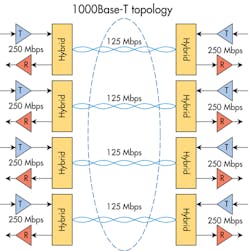
The 1000Base-T PHY employs full-duplex baseband transmission over four pairs of Category-5 (CAT5) balanced cabling. A data rate of 250 Mbps over each wire pair enables an aggregate data rate of 1,000 Mbps. Hybrids and cancellers allow full-duplex transmission, as symbols can be transmitted and received on the same wire pairs at the same time. Baseband signaling with a modulation rate of 125 Mbps is used on each wire pair. Transmitted symbols are selected from a 4D five-level symbol constellation. Each 4D symbol can be viewed as a 4-tuple (An, Bn, Cn, Dn) of 1D quinary symbols from the set {2, 1, 0, –1, –2} … Data is transmitted over each wire pair with five-level pulse-amplitude modulation (PAM5). The modulation rate of 125 Mbps matches the gigabit-media-independent interface (GMII) clock rate of 125 MHz for a symbol period of 8 nsec.
In addition, Clause 40.7.1 requires four-pair Class-D cabling with a nominal impedance of 100 Ω as in ISO/IEC 11801:1995. Cables, cords, and connectors must consist of Category-5 (CAT5) components as specified in ANSI/TIA/EIA-568-A:1995 and ISO/IEC 11801:1995. This CAT5e or “enhanced” cable is superior to CAT5 cable. The 1000Base-T architecture can run on existing CAT5 infrastructure, but the Ethernet Alliance recommends that new GigE installations use Category-5e cable.
CAT6 (250-MHz) and CAT6a (500-MHz) cables are also defined in ANSI/TIA/EIA-568-B and ISO/IEC 11801. They’re better than even CAT5e, mostly because of improved pair-to-pair isolation. Designed for 10 Gbase-T, CAT6 and CAT6a cables are sometimes used to improve performance “headroom” in GigE applications. New amendments to ISO/IEC 11801 even define a CAT7 cable (1,000 MHz) for possible use with 40‑Gbase Ethernet. IEEE 802.3 references to ANSI/TIA/EIA-568-A:1995 are replaced with four different specifications: ANSI/TIA/EIA-568-C.0, -C.1, -C.2, and -C.3. 568-C.2 is for balanced twisted pair cabling and components. However, old CAT5e requirements remain in the -C.2 revisions.
Thanks to PAM5 encoding — pulse-amplitude modulation that encodes information in five amplitudes of signal pulses — 1,000 Mbaud of full-duplex data transmits at an aggregate data rate of 500 Mbps. This efficient bandwidth use comes at the cost of more-noise sensitivity.
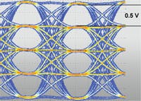
The signal-to-noise ratio is relatively low. PAM5 full pulse height is ±1.0 V and information is carried in relatively minute 0.5-V increments. The receiver must distinguish these 0.5-V digital pulses from noise voltages. In contrast, 100Base-T has the same clock rate but a pulse-voltage differential of 1.0 V — and a higher signal-to-noise ratio.
Additionally, differential noise from conductor crosstalk within the cable can degrade more active conductors. Unlike 10Base or 100Base that only carry data on two out of four cable pairs, 1000Base-T data travels on all four twisted pairs.
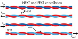
To solve crosstalk problems, a cancellation processor in the receiver reduces the effects of both crosstalk at the transmitter end of a cable pair, called NEXT, and crosstalk at the receiver, called FEXT. NEXT canceling is particularly effective (reducing interference by at least 20 dB) because the symbols transmitted by the three noise producers are available to the processor.
Adjacent cables can also cause crosstalk. Clause 40.7 limits the allowable level of this “alien” noise: Measured at the filter output on the output of the near end of a disturbed duplex channel, noise should not exceed 40 mV peak to peak. For this measurement the filter is a fifth-order Butterworth with a 3-dB cutoff at 100 MHz.
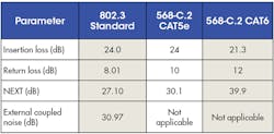
The 802.3 Standards committee bases their signal-to-noise ratio and timing jitter limits (listed in 4.6 and 4.7 of the 802.3 standard) on the cancellation and compensation capabilities of Ethernet electronics. (Refer to the 1000Base-T performance requirements chart for specifics.) Cabling requirements in ANSI/TIA/EIA 568 and ISO/IEC 11801 defines copper cable up to 100 m that maintains signal quality to these standards.
Slip-ring effects
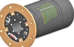
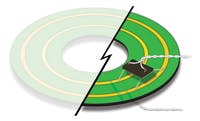
On the physical level, putting a slip ring into a 1000Base-T cable network requires one ring-and-brush set for each of the CAT5e cable’s eight conductors. However, the transactions within a slip ring — wire to ring to brush to wire — don’t need to mirror cable specifications to work well.
On the electrical-signal level, two items often cause engineers concern. The first is the sliding contacts themselves, and the possibility that intermittent contact from brush bounce or contact-resistance noise might cause random jitter. In fact, most high-performance slip rings transfer signals across rotating interfaces through precious-metal electrical contacts that minimize resistance variations during sliding. Typical values of 20 mΩ cause noise that’s less than 0.2 mV, two orders of magnitude less than the allowable coupled noise value of Clause 40.7.6. This –74-dB noise contribution is insignificant compared to other noise sources.
Bigger potential problems are the slip ring’s effect on frequency-dependent qualities and the potential for deterministic jitter. Impedance matching, crosstalk protection, and low attenuation all help. But inevitably slip rings affect all the parameters listed in the 1000Base-T performance requirements chart. TIA/EIA 568 cabling specifications provide no guidelines for evaluating noncable, nonconnector hardware, but there are three test options that can help specify slip rings (or other nonstandard hardware) and quantify effects on the 1000Base-T system’s performance.
1. Connect 100 m of CAT5e, CAT6, or CAT6e cable to the slip ring. Then test it on a GigE tester that returns a pass/fail report and data on all parameters required by TIA/EIA 568.
This specification allows only the effects of the 100‑m cable, so the slip ring is essentially prohibited from affecting any performance parameters. There’s a little difference between the IEEE 802.3 specification and the allowable values of a 100‑m CAT5e cable, so some high-performance slip rings can “squeeze in” under the margin. However, use of this specification strategy severely limits the size, complexity, and flexibility of slip rings and other nonstandard hardware.
2. Connect the slip ring to some portion of a 100‑m cable and test it on a standard GigE tester. Data should be normalized to the 100‑m cable attenuation, because the signal-to-noise ratio is the critical performance parameter. This method essentially allocates an equivalent cable length to the slip ring: For example, if an Ethernet installation requires only 20 m of cable, the slip ring is tested with that length of cable. The tester then evaluates them together against the 1,000‑m requirement, so the slip ring is essentially allowed to affect the design as 80 m of cable would.
Both the ANSI/TIA/EIA 568 cable and 802.3 Ethernet specifications are conservative, so there’s no reason to add a safety factor or cushion by adding cable length in this test. In addition, don’t use CAT6 or 6a cable to define performance parameters or evaluate slip rings, as this just reduces design flexibility. Instead, use the CAT5e requirement, because it is closest to the actual IEEE 802.3 specification. Use CAT6 or 6a cable later — in the installed design — if it needs more of a design margin.
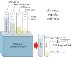
3. Develop a system loss-and-noise “budget” and compare it with that of the Ethernet specification or the designed system’s transmitter and receiver. This method is most useful where network performance parameters are wildly different from standard 802.3 values. The link budget can be defined using values from cabling and connector standards, published specifications for the slip ring, and specifications for the Ethernet transmitter and receiver. Then creative solutions can be used to accommodate the slip ring’s presence: For example, CAT6 instead of CAT5e cable can be used to “buy” loss-and-noise margin. This approach provides the greatest flexibility in choosing a slip ring to deliver required performance.
DefinitionsAXT (dB): Alien crosstalk. This is the coupling noise induced on a cable by other cables in proximity. Attenuation (dB): The reduction in signal power through a cable or interconnect; also known as insertion loss. Delay skew: The difference in propagation delay between any two pairs within a cable. FEXT (dB): Far-end crosstalk — the coupling noise induced on other pairs of a cable by a single energized pair of the cable and measured on the receiver end. NEXT (dB): Near-end crosstalk — the coupling noise induced on other pairs of a cable by a single energized pair of the cable and measured on the transmitter end. Return loss (dB): The loss in signal power that results in reflections from discontinuities in the transmission line. SNR (dB): The ratio of the signal power to noise power level.
|
