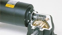
Gears, the universal symbol of productivity, have been a major cog in industry for hundreds of years. Before electromagnetic rotating machines were even a glimmer in Michael Faraday’s eyes, there were gears.
Early gears were made from wood with cylindrical pegs for cogs. They were often lubricated with animal fat, vegetable oils, and even water. Gears were used then for the same reasons they are now — because of their force multiplying properties. You’d find them on ships (hoisting anchors), in catapults (tensioning fly arms), and on a variety of machinery powered by wind and water wheels.
This file type includes high resolution graphics and schematics when applicable.
Metal gearing didn’t take off until the British industrial revolution in the eighteenth century. Since then, the science of gear design and manufacturing has come a long way, and continues to improve with advances in metallurgy, computer modeling, and CNC machining.
Gear types
There are many types of gears available today, each with specific advantages and limitations. Topping the list — at least for big jobs — are worm, spur, and helical gears.
Spur gears by contrast are more likely to produce noise, less tolerant of shock compared to worm gears, and slightly more expensive. On the plus side, they are compact, efficient, and available in parallel-shaft arrangements. They’re also easy to find because many manufacturers produce them. Spur gear ratios are generally 10:1 per stage.
Helical gears are similar to spur gears, but they have angled teeth. Because helical gears have more tooth contact area than spur gears, pound for pound they can carry heavier loads, though not quite as efficiently. They are somewhat more expensive as well and, depending on the configuration, may produce thrust loading on the bearings. Versatility is a plus, however, as helicals can be used on non-parallel, even perpendicular, shafts, achieving a 10:1 ratio per stage.Determining ratio
The standard approach when designing a machine is to select a gear ratio that converts motor speed to the desired rpm of the machine. The motor should be selected first based on factors such as available power, speed range, starting frequency, reversibility, torque, and so on. The sidebar comparing common motors will point you in the right direction for most applications.
Suppose you’re working on a fixed-speed application and you decide to go with an ac induction motor. In most catalogs, ac induction motors are available with base output speeds of 850 to 3,450 rpm. If the desired speed (for the machine) is 58 rpm, and you were using a 1,750-rpm motor, you would calculate gear ratio as follows:
Determining torque
For simple load-transmission applications, an easy way to determine the required torque is to attach a pulley to the drive shaft and wrap a cord around it (anchored with a spring scale). As you pull on the cord, the scale will tell you the amount of force you’re exerting. Do this several times and average the readings.
Torque is the product of force and distance from the centerline of the shaft, that is, the scale reading times the radius of the pulley. To lift a 90 pound load using a 2 ft. drum, for example, a gearmotor would have to produce:
If you know the speed of the drum, you can also calculate the required power. Say the drum speed is 58 rpm; then the amount of horsepower is:
Torque & rotating mass
For applications involving heavy rotating masses — such as flywheels, large conveyor rolls, rotating tables, and drums — additional torque is required to bring the machine up to speed. Here, you’ll need to consider load inertia WK2 in order to choose the right gearmotor.
Inertia loads invariably use more power to start and accelerate than they do to maintain running speed. The torque to accelerate load inertia WK2 may be calculated from:
where Torqueinertia is in poundfeet (lb-ft);WK2 is in lb-ft2; time is in seconds; and 308 is a conversion factor. The torque required to accelerate the load from standstill to running speed varies inversely with the time allocated for acceleration.
As an example, if the application has a load inertia of 480 lb-ft2 and an acceleration time of 0.5 sec to 58 rpm:
Note that the “actual torque” to accelerate the entire machine must also include transmitted torque.
The machine, therefore, requires a starting horsepower (to get the load moving) of:
Once the actual horsepower (torque) is determined, it should be multiplied by a “service factor.” This adds a safety margin and is critical in the selection process. Service factors for various machine load classifications are included here for convenience.
Suppose you’re working on an application with uniform shock loading that runs ten hours a day. From the table, the service factor multiplier is 1.00. Using the application (actual) torque calculated previously
Overhung load
An overhung load is a force applied at right angles to a reducer shaft. The problem with such a load is that it causes a bending force in the shaft that must be resisted by the reducer shaft as well as the bearings.
To get a better feel for overhung loads, consider a gearbelt transmitting 271 lb-ft of torque through a 10-in. diameter sprocket. The resulting overhung load is calculated as follows:
where “factor” depends on the coupling mechanism.
To make sure your gearing is up to the task you need to refer to a selection table (attached). The application calls for a 30:1 ratio, a 1,750-rpm motor, and has a required output torque of 271 lb-ft, or 3,252 lb-in. The smallest capable unit (size “400FC”) has an overhung load capacity of 1,950 lb, well within the application requirement.
All manufacturers’ specs and ratings are based on testing. Since your application may differ radically, it’s important to get a sample and test it under the actual operating conditions.
John Mazurkiewicz is a product manager with Baldor Electric Co., Fort Smith, Ark.

