Sending Signals: Sorting Out Single-Cable Sensor Connectivity

While sensors and low power actuators occupy the lowliest level of an automation system, they often require a disproportionate amount of time and attention. Historically, each sensor added entailed more power drops from the cabinet and electrician time to wire, plus more engineering time to configure and MRO staff to troubleshoot and maintain.
However, the desire for more data has steadily grown in the last decade as automation systems increased in complexity and manufacturers look to leverage manufacturing data as a resource. For example, sensor data can now help spot impending failures early, so they can be addressed in a scheduled, rather than panicked, fashion.
Additionally, real-time sensor data forms the basis for metrics like machine performance, availability and product quality that culminate in Overall Equipment Effectiveness (OEE), calculated on a minute-to-minute rather than weekly or monthly basis. Combining that with IT data from systems further up the stack (e.g. ERP, MES, WMS, etc.) allows for the optimization of critical functions such as production scheduling, warehouse inventory management and delivery performance.
Of course, theorizing about Industry 4.0’s potential benefits is one thing; realizing them in a real-world application is another. While the rest of operations, from the PLC up, have largely settled on a common data transportation mechanism, the “final meter,” from the controller down, remains an automation challenge. To remedy this last meter problem, the industry has developed and refined a handful of “single cable” technologies designed to simplify the installation, integration and maintenance of sensors so that collecting more data doesn’t just mean more headaches and expense.
The Dominant Player: IO-Link
The most successful of these, to date, is IO-Link. According to its governing body, Profibus and Profinet International (PI), the technology has experienced meteoric growth since the IO-Link standard (IEC 61131-9) was published in 2013. The organization predicts it will reach roughly 61 million nodes in the field in 2025. IO-Link’s popularity stems from the relative simplicity of installation, automated parameter setting and diagnostics and greater visibility into the lowest level of the stack.
READ MORE: IO-Link Masters: Enabling Sensors and Devices to Communicate Through Software
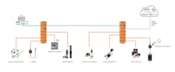
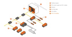
A bi-directional point-to-point network, IO-Link works on a master/field device architecture. Being point-to-point, each field device connects to one port on an IO-Link master using standard M5, M8 and M12 connectors. The master then functions as a gateway device “translating” sensor data from the IO-Link protocol to any of a wide range of common fieldbus systems including Profibus/Profinet, AS-i, DeviceNet, EtherCAT, EtherNet/IP and Powerlink, as well as mappings for IIoT-friendly technologies such as MQTT, OPC UA and JSON.
Also attractive is the ease of installation for an IO-Link network. Both power and data are carried over a single standard sensor cable. For power, a 24V DC supply connects to the IO-Link master which distributes the power to as many as eight class-A and/or class-B ports on the master. Designed for sensors, typical class-A ports supply up to 200mA, while class B ports serve actuators and some sensors that require more than 200mA.
For data, all IO-Link traffic is digital, eliminating the need for analog to digital conversion, and data values are reported in more precise true units, rather than the estimated values of 4-20mA analog signals. Between an IO-Link master and sensor, cyclical input and output process data is exchanged in 1 to 32 bytes (256 bits) per cycle, and in one of three data rates: 4.8k, 38.4k and 230.4k Baud. Update speed, however, depends on the amount of data exchanged (less data; faster rate) and the capability of the IO-Link field device itself.
The typical signal transmission time for one sensor is 2ms (milliseconds) for a 16-bit value; however, adding more sensors per master, using maximum cable lengths or 32-byte values increases transmission time. Process data is then cached in the IO-Link master, which is configured to transmit data at a rate required by the fieldbus architecture.
Beyond cyclic data, an IO-Link master and field device also exchange acyclic data, including basic device information such as serial and model numbers as well as more advanced data. This data is contained in an IO Device Description (IODD) file, a human- and machine-readable xml file format stored in a PLC or controller. The IODD file functions as an electronic nameplate for the sensor, defining its data structure and contents, as well as its basic functionality and diagnostic data. Since each IO-Link device has a unique but standardized IODD file, devices from different manufacturers can cohabit the same network.
IO-Link sensors and field devices also communicate event and diagnostic data via 2-byte hexadecimal error codes that pertain to faults such as a short circuit, configuration problems or access issues. When a fault occurs, the controller interprets the code based on a lookup table in the IODD file and alert users to the specific problem.
READ MORE: Unlocking IO-Link: What it is and Why it Matters for Modern Automation
In addition to the IODD file, an IO-Link master is configured with the parameter settings for each IO-Link device connected to it. In a maintenance context, this allows a faulty sensor to be replaced by an identical replacement without having to manually configure the new sensor. Upon identification of a new or replacement device, the IO-Link master downloads the desired parameters to the IO-Link device. IO-Link sensors can also be reconfigured by a controller on the fly to accommodate a changeover in production.
According to ifm Efector product manager, T.J. Berlin, IO-Link’s smart sensor capabilities provide one of the protocol’s central benefits for automation systems.
“If you take something like a traditional flow sensor, it has two outputs through which you can output one or two analog signals, or maybe an analog signal and a switch point,” he says. “If you move that same sensor to IO-Link, you’re not limited by the number of pins or outputs; you can ask that sensor what specific values are every time the PLC cycles, to get a whole range of parameters. So, with IO-Link, you get not just the flow rate and a totalizer, but also velocity, temperature and line pressure. All that previously trapped data is now available to the controller or to higher-level industry 4.0 systems.”
In addition to the above capabilities, the IO-Link standard also supports IO-Link Safety, a separate functional safety communication layer. An FS-Master connected to FS-Devices in an IO-Link network meets the safety standard for applications that require SIL3/PLe certification. It should be noted that IO-Link Safety (IEC 61139-2:2022) is relatively new, and therefore IO-Link Safety products certified under the international standard are still making their way onto the market.
Despite its many improvements over traditional sensor technology, IO-Link does have potential shortcomings. For example, cables can’t exceed 20 meters from master to field device. Another is the protocol’s relatively slow cycle time, which can make it ill-suited for high-speed motion control applications.
Functional Safety at a Distance: AS-Interface
In situations where IO-Link doesn’t meet requirements, AS-Interface (AS-i) may make it a better fit, especially for functional safety applications. Like IO-Link, AS-i (IEC 62026-2:2008) also transports power and data on a single cable and works on a master/field device architecture where the master functions as gateway to higher-level industrial networks.
Unlike IO-Link, however, AS-i is a fieldbus system which allows for typologies beyond point-to-point, including star, ring, tree, etc. In addition, an AS-i power supply delivers 30V DC and up to 8 amps to accommodate a wider range of devices or more devices per run, although standard 24V DC power supplies can be used.
AS-i uses a unique two-conductor flat cable that can extend up to 100 meters per cable run, or up to 300 meters with repeaters in most typical installations. Secondary or worker devices connect to the cable using AS-i’s piercing technology; modules, junction boxes and other AS-i equipment feature metal “fangs” that bite into the unshielded cable’s insulation to make contact with the conductors. As a result, sensors and actuators can be quickly installed or repositioned anywhere along the cable.
Over its history, the AS-i has developed four versions of the standard so far, each with increased capabilities. For example, standard AS-i (also referred to as version 2.0) allows for a master to address up to 31 nodes with a maximum of four inputs/outputs per node (analog or digital) with a cycle time of 5ms. An extended AS-i (version 2.11) master allows A-type nodes to be paired with A/B nodes, both of which share the same address, extending total nodes to 62 (31 A type; 31 B type). Over two cycles, the total 62 nodes can be scanned in 10ms (5ms per cycle). Standard AS-i (v2.0) modules support 248 binary inputs and outputs, while extended AS-i (v2.11) supports 8 inputs and 8 outputs for a maximum of 496 inputs and outputs per AS-i network.
Launched in 2004, AS-i specification V3.0 (ASi3) added Safety at Work (ASIsafe), a separate functional safety data channel over which ASi3 nodes—such as emergency stop buttons, light curtains and other safety I/O modules—transmit signals to a safety monitor. The integration of the safety monitor and ASi3 safety nodes provides safety certification to SIL3/PLe.
READ MORE: Smart Sensors: IO-Link Enables New Era for Strain Gauge Sensors
The latest version of the protocol, ASi5, retains the capabilities of, and is backwards comparable with, previous versions, but increases the number of nodes per network, data signal bit rate and scan speed. For example, an ASi5 master can address up to 96 ASi5 nodes and transmit 32-bit data as opposed to the 4-bit chunks for previous versions. In addition, 24 nodes can be scanned in as little as 1.2ms or the maximum 96 nodes allowed in 5ms per cycle.
It should be noted that AS-i has seen greatest traction in logistics applications like conveyance systems or those that require functional safety at a distance from the controller. Even so, the market may be retreating from AS-i. Ifm Effector, for example, has decided that, while it will support ASi3, it won’t embrace the ASi5, given that capabilities between it and IO-Link are largely synonymous, Berlin says. Likewise, Phoenix Contact says that it “strategically withdrew from the market for AS-i components in 2020.”
One PHY Layer to Rule Them All: Single Pair Ethernet (SPE)
An outgrowth of the auto industry’s desire to replace CAN Bus, Single Pair Ethernet (SPE) is the new kid on the block but promises the ultimate solution—that is, one physical layer (i.e., Ethernet) connecting every component in an industrial network from the cloud down to the lowly field device.
SPE falls under the same IEEE 802.3 standard as common Ethernet, but it doesn’t use the same 4 or 8 conductor twisted pair cables (e.g., CAT 5/CAT 6). As the name implies, both power and data are carried over a single pair of conductors, while retaining the performance of standard Ethernet cable.
For industrial applications, the SPE protocol is governed by three IEEE 802.3 sub-standards that define different performance levels for point-to-point connections. IEEE 802.3cg (also known as 10BASE-T1S or 10BASE-T1L) allows for 10MBits/s data transmission speed over cable lengths up to 1km but at a bandwidth of 20MHz. IEEE 802.3bw (100BASE-T1) ups the data rate to 100MBits/s and bandwidth to 66MHz but only allows for 40m cable runs. Finally, IEEE 802.3bp (1000BASE-T1) supports 1GBits/s and 600MHz bandwidth but with maximum cable run of 40m.
As an aside, Ethernet-APL, another single cable solution, is an offshoot of 10BASE-T1L that offers additional features tailored for process automation applications, especially those in potentially explosive environments (i.e., intrinsic safety).
No matter which of these 802.3 sub-standards, each supports Power over Data Layer (PoDL). Similar to Power over Ethernet (PoE), PoDL (IEEE 802.3bu) employs power sourcing equipment (PSE) that looks for a Zener diode within the powered device (PD), aka field device, to determine if the PD is PoDL-compatible or not. If it is, the PSE and PD exchange digital data using the serial communication classification protocol (SCCP) to classify the PD before power is applied to the Ethernet cable.
Initially, PoDL recognizes 10 power classes ranging from 12, 24 or 48V DC power and 0.5 to 50W at the PD. As of 2021, PoDL also encompasses Single Pair Power over Ethernet (SPoE) bringing the class total to 15 to allow 10BASE-T1L implementations to span cable lengths up to 1 km. Typical PoDL cable and connectors are rated to 1.36A maximum; however, the standard also allows for hybrid SPE cable with M8 and M12 form factor connectors to deliver as much as 16A.
Since modern fieldbuses also use the Ethernet physical layer, SPE doesn’t require master/gateways as in IO-Link or AS-i. Instead, SPE field devices and sensors connect to a PLC via managed SPE switches. Individual nodes are addressed by IP address and/or MAC address, similar to any TCP/IP-based network.
Being Ethernet based, SPE can also employ Time Sensitive Networking (TSN) to add determinism to network traffic. Under the IEEE 802.1AS standard, TSN allows all network devices to synchronize to a common clock, minimizing time drift, latency and jitter in data transfers. TSN also employs traffic scheduling to manage data timing, while the IEEE 802.1Qbv standard defines the assignment of high priority time slots for critical traffic types (e.g., an emergency stop). TSN also provides for bandwidth reservation to ensure real-time data has enough bandwidth allocated.
READ MORE: The Future of Industrial Connectivity: Trends and Challenges at Weidmuller USA
As to hard numbers, scan time for an SPE with TSN in the microseconds (μs) with near-1μs jitter depending on the number of nodes and switches employed and overall network traffic. For comparison, between its gigabit transfer speed and deterministic capabilities, SPE with TSN falls in the performance range of Mitsubishi’s CC-Link IE but with the addition of power delivery over the same line.
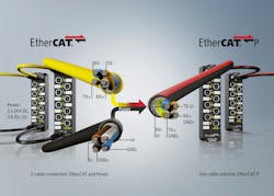
Uncompromising Performance: EtherCAT P
SPE isn’t the only Ethernet-based protocol looking to integrate field level devices into the rest of the automation network. EtherCAT P, an extension of the EtherCAT protocol standard (IEC 61158-1), also provides 24V DC of power, but over a standard twisted pair Ethernet cable. More precisely, EtherCAT P provides two electrically isolated power sources—Us for system and sensor supply and Up for actuators—each delivering 24V DC and up to 3A to EtherCAT field devices. On the data side, EtherCAT P cables provide the same full-duplex 100 Mbit/s capacity as standard CAT 5 Ethernet.
As to topology, EtherCAT P allows for those common for bus systems (star, ring, tree, etc). Layouts begin with an EtherCAT master connected to either an EtherCAT P coupler (for a star layout from the panel) or an EtherCAT P junction box (for a linear or tree layout in the field). Both a coupler or junction box is where a 24V DC supply adds power to the EtherCAT P segment of the network.
Beyond this point, EtherCAT P “hubs” can be daisy-chained to extend the network. Junction boxes and hubs feature multiple M8 connector ports specifically designed to prevent a non-EtherCAT P worker from being plugged in. If a power boost is required, additional junction boxes can be installed anywhere along the cable run.
An EtherCAT P network can address up to 65,535 devices, each of which can transmit process data from 1 bit to 64 kbyte. In addition, EtherCAT P retains the capabilities of standard EtherCAT including cycle times of less than 100μs (microseconds) and distributed clocks for precision synchronization of less than 1μs.
While EtherCAT may sound similar to Power over Ethernet (PoE), Beckhoff Automation Product Manager Azad Jafari points out the two are distinctly different.
“Ultimately, EtherCAT P is deterministic; Power over Ethernet is not,” he says. “In addition, with PoE you layout the typology through switches. With EtherCAT P, there are no switches; you can daisy-chain devices so you can go from the main controller to a EtherCAT P device to a sensor. This way you can eliminate the time delays inherent in the use of switches.”
Although EtherCAT P boasts impressive performance, it should be noted that, as yet, it’s utility favors actuators rather than sensors. According to the EtherCAT Technology Group, there are very few EtherCAT P enabled sensors on the market and they are produced by only a handful manufacturers.
In the final analysis, it seems the discreet manufacturing market has embraced two of the four single-cable technologies listed above, one mature and stable but hampered somewhat by its limitations; the other is new and still in development but highly promising. The impression is that SPE could significantly transform how automation systems are designed and operate, in that it removes one of the final material barriers to true Industry 4.0 implementation. In the coming years, it will be interesting to see if the industry embraces the new protocols like SPE, stick with the more established IO-Link or fashion a combination of the two.
About the Author

Mike McLeod
Senior Editor, Machine Design
Mike McLeod, senior editor of Machine Design, is an award-winning business and technology writer with more than 25 years of experience. He has covered the full spectrum of mechanical engineering, from industrial automation, aerospace and automotive, to CAD/CAE, additive manufacturing, linear motion and fluid power.
Voice Your Opinion!
To join the conversation, and become an exclusive member of Machine Design, create an account today!

Leaders relevant to this article: