As Automation Speeds up, a New Focus Falls on Component Handling
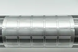
Manufacturers aim to shorten cycle times and maintain assembly accuracy consistently. Faster equipment helps, but speed alone cannot eliminate every production bottleneck. Automated material handling also depends on how efficiently each component reaches the assembly point. However, engineers often optimize materials and performance while giving less attention to how the component will enter the assembly process.
Oversight becomes vital with flexible, adhesive-backed parts such as seals and labels. Loose pieces may require extra steps to separate and position before placement. Continuous-liner presentation offers another approach by keeping each component organized. Designing parts around this controlled peeling process can shorten assembly cycles and help manufacturers gain more from automation.
Component Presentation is Part of Design for Manufacturing
Component presentation describes the physical format in which a part arrives at a workstation and becomes available for assembly. Design for manufacturing (DFM) expands this consideration by examining how design decisions affect component production and subsequent assembly.
In one modular home construction study, applying DFM principles reportedly shortened the design phase by 40% and reduced production errors by 48%. Although construction differs from industrial assembly, the findings illustrate that early consideration of manufacturing and assembly requirements can prevent downstream inefficiencies.
The same thinking applies to gaskets and labels. Engineers must consider whether these parts can be separated efficiently, rather than focusing only on their final dimensions and function.
Automated cutting can produce individual loose pieces, but those parts may require additional handling before assembly. Alternatively, die-cut components can remain positioned on continuous liners, creating a predictable presentation format that supports controlled peeling and placement.
How Component Presentation Affects Automated Material Handling
Efficient component handling is becoming more important as manufacturers invest heavily in industrial automation. The global market is projected to exceed $350 billion by 2028, which reflects the growing push toward faster and more automated production. However, faster equipment does not mean shorter cycle times. A mismatch can emerge when robots operate at high speeds, but component feeding and presentation remain slow or unpredictable.
READ MORE: Engineering Solutions for Reducing Wear in Bulk Material Conveyors
For example, individual components may require bins or dedicated feeding systems before a robot can retrieve them. Thin, flexible materials can curl or shift orientation, making reliable singulation difficult. Manufacturers may then need vision systems to create a consistent pick position. From a DFM perspective, faster automation offers limited gains when components are not designed and presented for efficient automated handling.
The Challenge of Picking Flexible Materials
Flexible components create unique challenges for automated material handling because conventional gripping methods depend on predictable surfaces and shapes. Vacuum cups may struggle to maintain suction on porous or irregular materials, while mechanical grippers can deform soft components during retrieval. Exposed adhesive introduces another complication, as parts can stick to tooling or neighboring components instead of releasing cleanly.
Dimensional flexibility can make robotic handling even less predictable. A component may appear flat and precisely defined, yet bend or sag once removed from its packaging or liner. As a result, its actual pick geometry may differ from its designed geometry, which makes consistent gripping more difficult. These variables can turn a seemingly simple pick-and-place operation into a significant source of cycle-time variation.
Designing the Part and Liner as One Manufacturing System
Kiss cutting separates the component material without cutting through the release liner beneath it. Finished parts remain precisely positioned on the liner, giving automated equipment consistent locations for retrieval. This format suits high-speed pick-and-place operations because robots can access regularly spaced components without first singulating loose parts.
Cutting only to the liner can also require less blade pressure than cutting completely through the material stack. Lower pressure may reduce blade wear, potentially extending tooling life and decreasing replacement frequency while supporting faster cutting cycles. These benefits demonstrate how upstream converting decisions can affect downstream throughput and operating costs.
How Peel-Based Presentation Can Reduce Assembly Time
Every assembly cycle contains handling steps that consume time before the component reaches its final position. A system may need to locate, orient and place each part. Indexed liner systems can simplify or eliminate several of these actions because automated cutting leaves components arranged at repeatable intervals.
Predictability allows a robot to repeat the same motion path with less reliance on individual part detection and orientation. Fewer handling steps can also make cycle times shorter and more consistent across long production runs. As those seconds accumulate, manufacturers can increase parts-per-hour throughput and make better use of existing automation capacity without simply increasing robot speed.
The Cost Equation Goes Beyond the Price of the Component
Engineers should evaluate the total installed or assembled cost rather than selecting a delivery format based solely on piece price. This calculation begins early on, when decisions can commit significant product life cycle costs during the design phase. Integrating manufacturing and quality requirements at this stage can reduce complexity as a component moves from development into production. Component presentation deserves the same consideration because a seemingly inexpensive format can create costly downstream requirements.
READ MORE: Computer Vision Transforms Production and Quality Control
For example, loose pieces may carry a lower initial cost but require feeders or additional labor for reliable handling. Continuous-liner presentation can increase converting or material expenses while simplifying component feeding and automated placement. Manufacturers can make a more complete comparison by calculating cost per successful assembly, including cycle time and handling equipment.
When Continuous-Liner Presentation Makes the Most Sense
Continuous-liner presentation works particularly well for membrane components, labels and insulating films. These parts often become harder to orient and position when supplied individually. The approach offers greater value when components are adhesive-backed, difficult to orient or required in high production volumes.
Individual pieces still make sense in some applications. Low-volume production or processes requiring substantial operator flexibility may not justify a continuous-liner format. Engineers should therefore evaluate the entire assembly process, including volume, equipment and changeover needs. Liner presentation works best when its handling advantages align with the demands of the production line.
Design the Component for the Assembly Line, Not Just the Drawing
Automation performance depends on what happens before a robot begins its primary assembly motion, making efficient automated material handling crucial to the process. Cutting method, liner selection and peel behavior can determine whether components reach assembly predictably or create recurring production bottlenecks. By treating component presentation as a DFM decision, manufacturers can simplify automation and increase throughput without necessarily redesigning the component’s core function.
Have a question, comment or idea? Get in touch with the Machine Design editors at [email protected].
About the Author
 Emily Newton
Emily Newton
Emily Newton is a technology and industrial journalist. She is also the editor in chief of Revolutionized. She has over five years covering stories about warehousing, logistics and distribution.
Voice Your Opinion!
To join the conversation, and become an exclusive member of Machine Design, create an account today!
 Leaders Logo
Leaders relevant to this article: