Three drive-networking rules to reduce electrical noise
Machines automated with electric actuators and drives are flexible, powerful, and easy to use. But such machines often operate in harsh factory conditions subject to electrical noise. This noise is present in all circuits, and in actuated machines, it stems from nonproductive signal fluctuations disrupting control signals and causing erratic actuator movements and even system failures.
The noise can’t be eliminated completely, and no communications are failproof. Therefore, the best approach when designing drive-based machines is to mitigate risks associated with each type of electrical interference and opt for communications priced appropriately for the application and seriousness of risk should the system fail.
More specifically, in electrically driven machines, noise with sufficiently high amplitude causes communication errors. Therefore, factory engineers should maximize the signal-to-noise (S/N) ratio by lowering the noise amplitude to a level that doesn’t interfere with the reliability of the control signal. There are three ways to do this.
FIRST OPTION:
Lower ground-loop noise
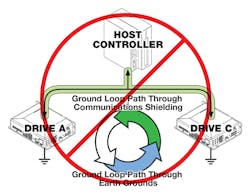
Ground loops cause most electrical noise and occur in poorly designed or installed systems that are either improperly designed or improperly installed. In a ground loop, unwanted currents flow through conductors joining two points of a given circuit that are supposed to be (but aren’t) at the same electrical potential. It is usually the result of two components connected to two different earth grounds. If these two grounds are at different potentials, a spurious current flows, introducing noise into the communication network. The voltage-potential difference usually comes from high-current electrical devices such as motors or compressors, or poor-quality or corroded ground connections. Current flowing between the different earth grounds injects electrical noise directly into the circuit and appears everywhere.
Making matters worse, many drives may be connected to the same CANopen, Ethernet, or RS-485 communication bus. Communication cables are typically shielded with foil, braid, or both. However, for shielding to be effective, the shielding material must connect to ground. This means all of the drives connected to the same communication bus must connect to one ground, and it must connect to the host-bus controller.
Each drive is powered by its own power supply, which is typically plugged into a grounded power outlet. Unless all the drives and host-bus controller are plugged into one outlet, a ground loop can form. In fact, even a single drive plugged into an outlet with a different ground than the rest of the system can set up a ground loop. Unless a designer has complete control over the installation site, it’s almost impossible to predict where ground loops will appear. Therefore, ground loops can only be detected and mitigated after installation. But don’t ignore them: If ground-loop noise is great enough, it can make operation erratic or lead to complete failure.
There are two mitigation strategies for ground loop noise:
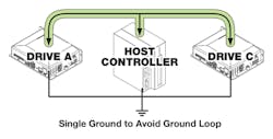
• Designers can build machines with a single-point ground to prevent ground loops.
• For large systems where single-point ground isn’t possible, designers can physically connect grounds and insert a small resistor between them. (Using 10-Ω resistors to start.) This limits current flow between the grounds to reduce noise and ensure potentials are relatively close to each other.
SECOND OPTION:
Lower induced noise
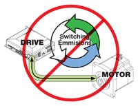
In servodrive circuits that use high-current switching signals with sharp edges — think pulse-width modulation — sections of circuitry can act as antennae and induce electrical noise in nearby conductors or equipment. This is called electromagnetic interference (EMI).
Power cables and communication lines can both transmit and receive noise. EMI noise coupling stems from electromagnetic noise emitted from the drive is picked up on the power cables or communication lines. Power cables and communication lines can also induce noise into a nearby drive. This coupling magnifies the noise internally and can cause communications failures and device instability.
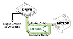
To address EMI, first measure this noise and certify the level of EMI in applications that employ switching signals. Measure EMI with the motor and communication cables plugged into the drive. Then minimize EMI by following good printed-circuit-board layout rules. Mitigation strategies for induced electrical noise include shortening motor and cable lengths, using properly shielded cables, separating the motor and encoder cables, and grounding only one end of the cable.
Make motor and communication cables as short as possible, as longer cables emit and receive more noise. Unnecessary coils of wiring also add resistance and inductance to the circuit, which can affect motor tuning. When routing cables, make sure they are mechanically secure.
Use properly shielded motor and encoder cables. Motor cables should be shielded with foil or braid to mitigate switching noise. Higher-quality cables that include foil and braid will help, but the additional cost needs to be weighed against the target level of reliability. Cable shielding should connect to ground through the drive connector. Communication lines should also be shielded per industrial specifications.
Separate the motor-power and encoder cables or use hybrid motor cable specifically designed to mitigate noise. Many times, encoder and motor-power cables share a connector to the motor. They also typically plug into connectors close to each other on the drive. The physical paths they take from the motor to the drive can be similar, but as a general rule, try to maintain at least 2 in. of separation between the cables to limit inductive coupling.
Cable shielding should be grounded on only one cable end — typically the drive end. Grounding shielding at motor and drive ends can generate ground loops.
The low-voltage signals industrial devices use to communicate data and controller commands are particularly susceptible to external electrical noise. That’s why most industrial communication protocols are designed to help signals survive noise. Typically, controllers are programmed with protocol firmware that detects errors and data loss in device-to-device communications.
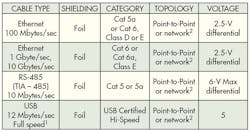
Cables also protect signals from outside interference. Shielding wrapped around the data conductors directs stray noise to ground, and the twisted conductor pairs let the receiver in the controller compare signals and cancel out the effects of EMI. Designers should make cabling as short as possible so it doesn’t coil. It should also go through areas in the plant that don’t induce noise. Designers should pick the one of these cables based on application requirements while adhering to 1 and 2 as noted in the table below.1. USB connections aren’t recommended for industrial environments because they have low signal levels. In addition, they need signal filters because industrial-grade noise degrades their reliability. Unfortunately, such filters also keep out high-speed and superspeed communications. Therefore, most actuator drives come only with full-speed cable options, and USB cables are used only for initial configuration (and not for ongoing control).
2. Most industrial communications require twisted-pair shielded cable for differential communications.
In addition to following these guidelines for picking the right cable, remember that the main artery of any automated machine is the communication link between the drive and PLC controller. Severing communications can stop the machine. Follow these guidelines to prevent such outages:
• For Ethernet communications, use a fully managed Ethernet switch that is rated for industrial use. Keep in mind that electromechanical actuators are typically installed in electrically noisy environments. This means that standard off-the-shelf communication switches and hubs may not have enough power or protection to do the job efficiently. Numerous options for network switches and hubs are available online. Pick switches rated for the installation environment. While unmanaged switches may work for a given installation, managed switches are programmable and can configure and monitor the network. This lets engineers fine-tune designs and detect problems as they arise.
• Make sure all communication cables are secure to reduce wire fatigue. Communication lines are made from various types of copper. Some are more flexible than others, but all tend to fatigue and weaken if bent and unbent repeatedly. That’s why continuous cable movement often creates weak spots that eventually break. Breaks can be hard to locate, and to make matters worse, broken pieces of wire can still touch intermittently, acting like good communication lines that only fail in certain positions.
• Use best practices when daisy chaining drives to maximize communication speed and minimize communication breakdowns. Some drives support daisy-chain communications to other drives. It lets designers use fewer network switches and less cabling to connect drive controls. But daisy chaining can slow communications, because each link in the chain must process all signal packets going through the network. Each link must also check to see if signal packets are addressed to it, forwarding or processing packets when applicable. Another issue is the survivability of the network should one communication line or device fail. Take heed, as all drives connected downstream either kind of failure point will cease communications in daisy-chained networks. To minimize the impact of failures, limit the number of drives in any daisy chain to a number appropriate for the application’s network-response requirements and the risk associated with a single device’s failure.
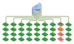
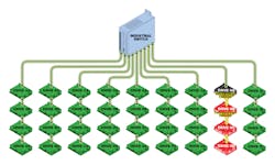
• Weigh the cost of installing all the drives against the safety and financial risks if part of the network shuts down. For example, a factory with 36 drives maintains fast response time and is unlikely to shutdown completely if drives are connected in nine sets of daisy-chained foursomes.
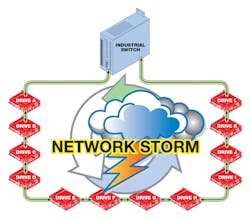
Avoid ring configurations and eliminate network storms. It’s almost never appropriate to connect daisy-chain architectures in rings. The problem is that messages erroneously forwarded back and forth through ring architectures cause network storm. Network storms are the cacophony of signals that arise when one node’s broadcasts get rebroadcast by other nodes and prompt more responses and rebroadcasts. The storms can be so severe that they completely halt all communications. Some high-end routers and switches support spanning-tree protocols and have dedicated hardware for ring connections, but they’re expensive. Daisy-chaining the network as in our 36-drive factory, with nine sets of foursomes, is a better setup.
