Cable Basics: Understanding Dynamic Load-Bearing Capacity
Choosing the best cable for an industrial application is one of the most critical design decisions of any complex automated system. Designers often select cables as an afterthought – not giving enough time to make a well informed decision. As the lifeblood of the system, cables and wires are vital to transmitting power and sending control signals and data across wide expanses in a timely and reliable manner. Here we take a look at some of the most important factors to consider when specifying industrial cable.
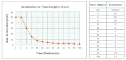
Wires and cables intended for use within cable tracks are subject to enormous loads. Especially in highly dynamic applications, several factors should be considered when choosing the right cable—durability, reduced weight, a small minimum bending radius and the ability to fit within tight spaces. Many of today’s automated production environments must meet rigorous productivity benchmarks, often requiring components to handle speeds of 5 m/s and acceleration of 50 m/s2, along very lengthy paths. To meet these demands, every component in the system must be optimized to work together, including the cable, wiring, cable tracks and carriers.
Knowing the specific application and industrial setting in which the cable track will be used will help determine the characteristics required in its interior parts—the cables and wires. A good place to start is to understand the physical forces acting on the system. Regarding mechanics, the following loads must be considered:
Push and pull loads - These forces act in the longitudinal direction of the wire.
- Static—Vertical forces such as gravity act on stationary cables (ex. fountain submersible pumps).
- Dynamic—Horizontal forces from acceleration/ deceleration act on the wires within the cable track.
- Static and dynamic—Cables moving vertically in cable tracks are subjected to both gravity and acceleration/ deceleration, for example in an elevator.
Bending Loads - Three distinct bending methods include the following.
- Simple flexing (tick/tock)—Flexing at a single, defined break point.
- Continuous flexing—Flexing that occurs along the entire cable length.
- Guided flexing—Continuous flexing using a guiding component. (ex. pulleys)
Cables used in tracks are exposed to bending along their entire length and are therefore subjected to continuous flexing. When specifying components for this type of use, it is important to choose a cable specifically designed to handle these forces.
Torsion Loads - Torsion flexing typically occurs in robotic applications. Special torsion-rated
cables are designed to withstand increased torsional stresses and feature a different construction than continuous flex cables. While continuous flex cable conductors are stranded tightly to allow relative movement of individual conductors during flexing, robotic cables have significantly longer lay lengths to compensate for more stressful torsional forces.
Generally, the following parameters must be considered: Required length of travel, maximum acceleration and speed, minimum bending radii of cables and wires, combined weight of all moving components (including the cable track and related cables), and desired life expectancy of the complete system.
Selecting The Best insulator - The molecular structure of a compound determines its fundamental physical characteristics, such as, fire resistance and the ability to withstand certain oils. In turn, these attributes determine the material’s suitability as a wire insulator. Polyvinyl chloride (PVC) dominates the cable insulation market, although other materials are also used, such as thermoplastic elastomers (TPE), polyurethane (PUR) and polypropylene (PP).
Each material offers unique features that make it suitable for different types of cables. For example, PVC offers relatively high mechanical firmness, good insulation resistance and flexibility at a reasonable price. In comparison, ether-based PUR guarantees microbe resistance and features high abrasion resistance, tensile strength, stability against certain oils and good flexibility.
In general, cables and wires in highly dynamic applications must withstand acceleration forces up to 50 m/s². However, acceleration is not the primary factor to consider when choosing materials—abrupt deceleration is far more critical. Within a fraction of a second, the cable brakes to a stop. Because of this, certain rigidity is indispensable, which can only be guaranteed by suitable insulation materials. Choosing the wrong materials will eventually lead to cable track fractures due to the extreme forces and highly dynamic acceleration and deceleration that the cable experiences on a continual basis.
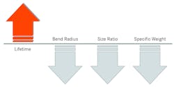
Jacketing Materials Are Another Important Consideration - Although it may seem intuitive to choose ultra-flexible material for cables used in moving tracks, relatively rigid, self-supporting materials actually achieve the longest cable life. Polypropylene insulation is common, due to excellent insulation properties combined with high strength and low density. This means less total material and a slimmer, lighter and more flexible cable. With smaller tracks and a reduced minimum bending radius, additional guiding systems can be installed in a smaller space. This reduction has the added benefit of decreasing the machine’s energy consumption for continuous acceleration and deceleration processes. In turn, the space saving and energy efficiency contribute to extended machine lifetimes, thereby boosting overall efficiency.
Bending Radius and Stranding Techniques - Cable insulation and jacketing materials inevitably wear out due to sliding and abrasive interaction with the track. Worn parts must be replaced and exchanged regularly. Maximizing cable performance and useful life lifetime requires rigorous testing protocols. Cables are subjected to intensive flexing tests to confirm their lifespan over millions of flex cycles. To simulate the wide range of real world conditions, various cable track test systems with differing travel lengths, speed and acceleration ranges are used in testing. To guarantee reliable operation in highly dynamic applications, traversing speeds of 10 m/s and accelerations to 100 m/s² can be tested.
With respect to bending radius, consider this rule of thumb: The larger the cable’s minimum bending radius, the greater the space requirement of the track in the machine. In addition to minimum bending radius and its impact on machine footprint, the cable’s physical structure also plays a role. Two different stranding techniques are commonly employed in industrial cable designs:
- Twisted in layers—Conductors placed in concentric layers around the pipe axis.
- Twisting in bunches—Collectively, multiple conductors in bundles that are stranded with other bundles around the pipe axis.
As a significant advantage, cables following in the twisted in layers design feature much smaller outer diameters, as well as ease of dismantling and jacket stripping. However, the bundle stranding procedure is only used with larger numbers of wires, typically more than 11 to 12. With regard to lifetime expectation, after numerous tests in Lapp’s laboratory, no considerable differences between the two stranding techniques emerged. One notable advantage of the bundled stranded wires is higher stability in relation to torsion loads. Due to the smaller outside diameter of twisted in layers cables, they also need less space in the track compared to cables twisted in bunches. This allows smaller tracks to be specified. It is important to note that cable track selection should only occur after the correct cables are specified, and not the other way around.
Further, the weight of the entire system’s cable track must be considered. Particularly in highly dynamic applications, weight is an important factor. The force that results from dynamic machine motion comes from the product of mass and acceleration. In order to avoid huge forces with related demands in terms of acceleration values, it is useful to reduce the mass of all moving parts. Besides the cable track, all other moving components including supporting elements and guide carriages must be taken into account. Another benefit is that the surface loading of the cable track is reduced, resulting in less energy consumption and allowing higher acceleration values.
Regarding installation techniques, it is important to keep the cable track’s traverse length as short as possible. In addition, specifying matching components that are designed to work together ensures smooth and reliable operation. Keep in mind that not every cable track is designed for acceleration up to 50 m/s². Particularly in highly dynamic scenarios, it is preferable for tracks to be as lightweight as possible and as firm as the application requires. Further, tracks must exhibit a certain twisting rigidity in order to stand up to the demands of fast moving and dynamic machine motion.
Separators should be easily reconfigurable as needed, and the abrasion behavior of cables and bars working together must be considered. If cables of different diameters are installed into to the track, it is important to make sure they are kept apart by separators to avoid tangling and disruption of signal and power transmission. Finally, installers must ensure that wires are free of twists when installing them into the cable track so that cables and wires can move freely within the bend radius.
Selecting a provider with rigorous comprehensive testing is key when specifying cables, especially for use in high speed, dynamic applications. Further, to avoid damaging cable tracks with frame bridges or perforated aluminum stays are preferable, because these designs ensure the least amount of unwanted interaction between the track and cable.
For more information please visit www.lappusa.com
Takeaways for Cable Selection |
|
• Extra stiffness better resists the additional stresses seen by cables subjected to high accelerations and decelerations. • It is important that high-acceleration cables be as light as possible to limit forces. • Roundness of the cable is important for a good connection and to keep dust and environmental corrosions out.
|


