How to Update Tools for Leak Testing for Big Data
Many components—such as those used in autos, appliances, and airplanes—undergo leak or pressure tests after production to ensure they are working safely and properly. Companies such as ours have developed sealing technology to isolate subsystems during such tests, honing the ergonomics involved and speeding up the process to increase throughput while ensuring connections don’t leak. Those were the basic goals for decades. Currently, however, many manufacturers that use leak-test equipment want to use big data to make manufacturing more lean, efficient, and safe.
Quick-Connect Basics
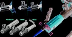
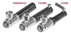
One of FasTest’s most popular products, the FasMate FN series, provides an efficient way to seal ports with female threads. The connector uses a split collet design that let the jaws collapse, allowing for an instant connection that is safe up to 5,000 psi. There’s no need for a wrench, pipe tape, sealant, or any other antiquated sealing method. The operator simply opens the connector, inserts it into the port, and closes it using one of three methods: lever, thumb valve, or pneumatic.
The lever requires that operators simply squeeze the handle. Both the thumb and pneumatic methods use air pressure to control the connector; one uses a built-in thumb valve and the other has an air-line port opened using a foot switch or other means.
All three methods collapse the collet so the connector can be inserted into a port. The collets’ jaws and center shaft are hardened stainless steel, which provides a balance of strength and wear characteristics. If the parts were too hard, they would be brittle and fracture after the repeated stress of high-pressure tests. And if they were too soft, they would wear too quickly. The stresses are distributed between the shaft and collets to ensure they work together. The shaft and collets are designed so that the end of the shaft is wedge shaped and pushes against the collets’ inner diameter, forcing them outward. This means the connector pulls itself into the port as pressure increases, making it safer and more effective during high pressure tests.
For a leak test, a fixture that delivers pressurized air is equipped contains a multi-jawed collet for quick connects and disconnects from an internally threaded female connector. Users wanted the sealing device to collect information to help them use a big-data approach to improving their products.
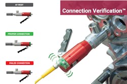
To meet manufacturers’ increasing needs for data points, FasTest added smart technologies into FasMate. Connection Verification (CV), for example, lets manufacturers verify successful, safe connections have been made before starting a leak test. It measures piston travel, and that information alerts operators when something has changed. It consists of a potted circuit board containing an LED to alert operators of good connections.
The connector can be configured in either a discrete (sinking/NPN or sourcing/PNP) or analog output. The discrete output lets operators know whether or not the main seal is in the calibrated range, and thus whether the connection was successful or not. Connectors with the analog output are particularly powerful because they communicate in real-time what is happening to the main seal. They work at either a 0 to 5 V or a 5 to 10 V range.
Regardless of the output, discrete or analog, the circuit board can be calibrated to show when the piston has moved to the correct position and alert both the operator and leak-test system that the connector is properly sealed, and the test can be safely run. This helps eliminate false failures.
A false failure is when a leak-free part fails a leak test. It might take a few consecutive failures before an operator realizes the parts are in-spec, but the test equipment is not working correctly. Examples of failure modes include incorrect and inconsistent pilot pressures, worn connector seals, and improper connector placement. False failures cost manufacturers time and money in the form of retesting and product scrap. CV-equipped connectors immediately alert operators something is wrong and the system needs to be checked.
All of the testing done while developing CV gave FasTest engineers a much deeper understanding of how FE and FI connectors act during use. These pneumatically actuated connectors use air sent through a pilot valve to compress the main seal on the part being tested. Engineers discovered that even small changes in pilot pressure affect piston location. Fortunately, this can be accounted for by properly calibrating the connector.
The connector can be activated pneumatically by a foot switch, by a thumb switch, or by a lever. Any of these three methods opens and closes the collet that makes a tight connection with an internally-threaded female connector hooked up to the device being tested.
“We also did a lot of seal wear testing,” says Rob Danielson, vice president of engineering at FasTest. “It revealed that the piston traveled further as the seal wore and we eventually learned to precisely predict when a seal would wear to the point of leaking. This means users can get the longest possible life out of the seals by replacing them just before they’re about to fail. Traditional quick connectors make users wait for a connector to fail, which wastes time, or to replace seals before the end of their useful life, which wastes money.”
Engineers also learned that the most important aspect of CV-equipped connectors is proper calibration. There are several ways to handle calibration. Users can wire it directly into the PLC and pass 24 V to the circuit board at the appropriate time. However, there are some nuances to that doing that properly, so the team devised a straightforward method they dubbed the Smart programming tool. Instead of wiring into a PLC, user connect to a programming tool plugged into a 110-V outlet. When users have the calibration points correct, they press the button on the tool to saves the locations in the circuit board’s memory. They remain there even if power is removed.
The first versions of CV connectors had circuit boards potted directly into their aluminum housings, which worked well but did have its drawbacks.
“We realized that the entire housing had to be replaced if anything happened to the circuit board or electrical connector,” says Danielson. “To help customers maximize the life of the connector, we made the circuit board a replaceable module. It is now enclosed in potting material and can be replaced if needed. This lets customers upgrade their connectors without replacing the machined components.
“We designed the module to fit each body size of FE and FI,” he continues. “There are 12 different bodies and the discrete and analog boards each need their own mold, so we created 24 molds. We needed to come up with a cost-effective way to create these molds due to the high-mix, low-volume nature of our products, so we used our 3D printer to create the plug or buck.”
The plug functions as a representation of the object that is to be molded. In this case, it was the module that would fill the cutout on each body size. As a result, developing the prototypes was much simpler sing the 3D printer.
“Once the plugs were printed and prepared, we used a premium room-temperature-vulcanizing silicone to create the molds themselves,” says Danielson. The silicone has excellent dimensional stability, high strength, and a long shelf life. It also has a low viscosity, so it easily flows into small features and captures a lot of detail. After the molds cured, Teflon knock-out pins are put in the circuit board and the boards are put into the molds. A two-part epoxy formulated for electronics encapsulation is poured into the mold. The epoxy’s low expansion coefficient means electrical components aren’t moved around or pulled off the board while the epoxy cures. It also has low viscosity and UV protection to minimize yellow. Finally, once the epoxy cures, the potted assembly pops out of the mold and the pins are knocked out. This has proven to be a fast, efficient way to make many different sizes of molds and ensure a consistent final product.
Connection Verification was initially developed for the FE and FI product series but was always meant to be incorporated into other FasTest products. One of the benefits of the potted circuit boards is that FasTest now had a modular design that could easily be retrofitted to other connectors. The next logical step for FasTest was bringing CV to its FasMate product line. FasTest was able to use two of the existing molds from the FE and FI connectors that were the same size as the back actuators of the FasMates. “There were some packaging difficulties that came up, but it was a fairly smooth marriage of the two technologies,” says Danielson.
There were some other unforeseen challenges that also came up. “We began testing the Smart FasMate and found that the way the connector reacts under high pressures made it difficult to set the calibration points,” says Danielson. “The lever version of the FasMate (FNL) is our largest seller and the one we spent the most time figuring out a calibration procedure for, while the pneumatic version (FNP) uses the analog circuit board and is easier to calibrate.” There are two calibration points: one at the low end of lever movement and one at the high end. The low end was giving FasTest issues. FasMate connectors use the wedge end of the shaft and internal pressure differences to pull themselves into the port being tested. This pulling action was enough to move the internal piston outside of the calibrated zone in some situations. This led to FasTest changing the connector’s software to make it easier for users.
“Now, all they have to do is set the first point when the connector is at rest (point A) and the software automatically jumps to a predetermined low point (A1),” explains Danielson. “This jump accounts for any internal movement during a high-pressure test. Then the user moves the lever to the second calibration point (B) and sets that.” In setting the high point within the overall movement of the lever, the user can see over-travel and under-travel conditions. The LED is off when the connector is at rest, showing under travel. The light turns on when the lever moves into an acceptable range, then turns off again if the lever moves outside that range, showing over-travel. “Adding Connection Verification to FasMate gave us insights into how the connectors were reacting during a test that we would not have been able to otherwise see,” says Danielson.
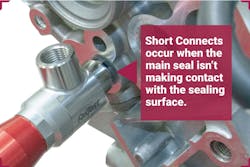
There are other benefits to CV. It prevent “short connects”, which happen when operators insert a connector far enough to engage the collets’ threads but the main seal isn’t contacting the sealing surface. With a short connect, the connector could leak during testing and lead to a safety issue. The LED on CV-equipped connector will not light up unless the connector is properly installed.
CV also helps train operators. Experienced operators might be familiar with FasMate and understand how to make a proper connection. However, if someone is new on the job, they might not understand how the tool works or lack the “feel” for how to make proper connections. With CV, the green LED lights up when users make a good connection. CV can also be a good tool for preventative maintenance. Operators can use signal outputs as data points to identify trends that show how long main seals are lasting. The process engineer can then set a preventative maintenance schedule to minimize downtime and rework caused by false failures. Perhaps most importantly, CV improves product quality. Manufacturers know that their parts and systems have been properly tested, and the product is fit for customer use.
The green light indicates a good connection has been made, while no light indicates a bad connection.
Beta Site Benefits
An important part of the development process was using beta sites to get real-world criticism on new products before going to market. “This helps us uncover issues that don’t show up in labs,” Danielson notes. “At the very least, it’s helpful to get additional feedback from someone who isn’t familiar with the design.”
Beta sights are typically identified by the company’s new product introduction (NPI) group. Once a test site has been confirmed, an engineer go set up the equipment and gather pertinent information. “At the end of the test, we have them fill out a questionnaire and return the connectors so we can tear them down and evaluate how they withstood the test,” Danielson says.
Jake Chandler is manufacturing division engineering manager at FasTest Inc, (651) 645-6266, www.fastestinc.com.


