Precisely controlling motion for twisting, winding wire cable
To make multiconductor communications cables, two or more insulated conductors are grouped together then twisted and wound on a reel. If desired, the twisted wires are then unwound from the reel and covered with a plastic coating, tape, electrical shielding, or a combination of these.
The twisting adds strength, flexibility, and electrical noise immunity. (Untwisted cables can pickup electrical noise produced by electromagnetic and electrostatic radiations. By contrast, the twists cancel the interference signals. Shielding over all the conductors in a cable further increases noise immunity.)
Engineers at Webster Machine Products, Webster Mass., wanted to improve the control of a 36-in. buncher cable machine. The previous design required complex setup procedures and never held a constant lay, the inches per twist. In addition, this manufacturer of custom cable- making machines, is expanding the machine capabilities. To do this, required integrating a new motion controller that would accommodate a wide variety of wire sizes, different values of lay (inches per twist), and various reel sizes. Plus, the sysem had to assure the specified lay would remain consistant throughout a production run.
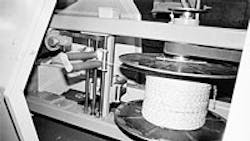
Two motors power the cable-making machine, called a flyer, that both twists and winds the conductors on a reel, Figure 1. Relatively simple, the flyer requires complex motion relationships based on five variables:
• Desired operating speed.
• Lay of the twist. This varies over a 16:1 range, from 0.5 to 8 in. per twist.
• Reel buildup, typcally reaching 2:1 with a full reel.
• Flyer motor speed.
• Reel motor speed.
If any of these relationship, which constantly change during operation, are wrong, a multitude of problems turn good product into scrap.
One of the complicating factors in this design is the relationship between the flyer and reel speeds, which determines the lay. For example, at maximum reel speed — empty core, longest lay of 8 in., and full line speed — the reel motor runs 37% faster than the flyer motor. By contrast, at minimum reel speed — full reel, shortest lay of 0.5 in., and slow line speed — the reel motor runs less than 0.5% faster than the flyer motor. Should the reel motor run ever so slightly slower than the flyer motor, the cable would unwind and wreck havoc with the whole system.
Two programmable motion controllers — M-Trim controllers supplied by Fenner Controls, Maple Grove, Minn. — solved these problems. Controller A, Figure 2, adjusts for the set line speed, buildup, required lay, and speed of the wires into the flyer as measured by encoder A. This encoder is turned by idler rolls through which the wires pass. Controller B establishes the speed ratio between the flyer and reel motors.
Operation
The operator adjusts the master linespeed potentiometer and enters the desired lay and other variables into the digital keypad in Controller A. This unit sends a trim signal to Controller B, which has been programmed with the parameters to establish the speed of the reel motor based on this trim signal and the speed feedback signal from the flyer motor. During operation, both controllers apply the programmed algorithms to establish the reel motor speed to maintain the set requirements.
A gear train between the reel drive and a linear actuator powers the traverse mechanism. Because this is an intermediate step in the cable making process, it is not essential to optimize the traverse speed to the diameter of the cable.
