Basics of Rotary Encoders: Overview and New Technologies

This file type includes high resolution graphics and schematics when applicable.
Rotary encoders track motor shaft movement for myriad pieces of industrial equipment and commercial devices. For industrial applications, incremental encoders (used when only relative position is needed, or cost an issue) are typically used with ac induction motors. In contrast, absolute encoders (which give a different binary output at each position, so shaft position is absolutely determined) are often paired with permanent-magnet brushless motors in servo applications. Often, encoder feedback is used to ensure synchronization of the motor stator and rotor positions to drive-supplied current, so current is applied to the windings when the rotor magnets are within a proper position range (to maximize torque.)
Rotary encoders are specified for form factor, level of ruggedness, and resolution. For incremental encoders, resolution is defined as counts per turn. For absolute single-turn encoders, it is positions per turn, expressed as a multi-bit word. Multiturn encoders (those that track over multiple 360° turns) are specified in positions per input-shaft turn, and the number of internal gear-ratio turns.
Required resolution depends on the number of positions requiring measurement. If a machine must measure the travel of a 25-in. leadscrew in increments of 0.001 in., for example, then it requires an absolute encoder with a resolution of 25,000 points. That said, resolution here is usually defined in terms of bits: A 12-bit encoder, for example, refers to the binary number 212 that is 4,096 decimal. Thus, a 12-bit encoder has a resolution of 4,096 points.
Accuracy (unlike resolution) depends in whole-system interations with the application, and is traceable to the encoding disc (a subcomponent we’ll discuss further) and the deviation between actual and theoretical position. A good 12 or 13-bit encoder, for example, is accurate to within half a count on the least significant bit.
Repeatability, the encoder’s ability to read the same point each time the shaft is in a particular position, is defined as the deviation of actual encoder position between subsequent identical code readings. Although it has no relation to accuracy, it is usually four to ten times better.
Side note on resolvers versus encoders
Technologically mature but proven resolvers (extremely rugged electromechanical devices with an electrified rotor and twin stator windings that pick up differing induced voltages, depending on shaft position) report absolute positioning with accuracy of 3 to roughly 50 arc-min., but are limited to 200:1 speed ranges and are associated with complex circuitry and installation. In contrast, easy-to-apply encoders are a suitable component for all but the most punishing applications, and they output inherently digital signals, better accuracy (typically 0.1 to 35 arc-min.), and speed ranges of better than 100,000:1.
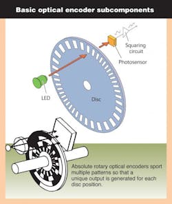
Rotary optical encoders
Rotary optical encoders, the most widespread encoder design, consist of an LED light source, light detector, code disc, and signal processor.
The disc has opaque and transparent segments and passes between the LED and detector to intermittently interrupt a light beam. The detector tracks the series of light exposures it receives and sends that information to the processor that extracts motion information.
Two rotary optical encoder subtypes exist: Incremental and absolute.
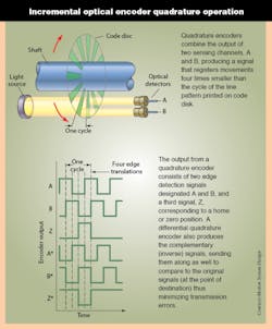
Incremental encoders are named for their output, consisting of the two square waves, each corresponding to an increment of rotation. Typically, the LED directs rays through a convex lens that focuses the light into a parallel beam; the beam passes through a grid diaphragm, which splits it to produce a second beam of light 90° out of phase. Light passes from A and B channels through a disc onto the photovoltaic or photodiode array. The disc rotation creates a light-dark pattern through the clear and opaque disc segments.
This pattern is read and processed by a photodiode array and decoding circuitry; beams A and B are each received by a separate diode and converted into two square-wave signals ... 90° out of phase, commonly known as quadrature output. It’s then fed into a processor that can process the signal to determine the number of pulses, direction, speed, and other information. Incremental encoders can also have a third channel with a single segment slot or reference that is used to zero or home the device. Alternatively, an incremental sine-wave encoder produces quadrature sine waves (sine and cosine) instead of square quadrature. Arctangent functioning yields arbitrary levels of resolution.
An absolute encoder has multiple detectors and a disc with multiple, unique tracks. The disc produces Gray code output — named after Bell Labs physicist Frank Gray — a binary numeral system for which (unlike straight binary) successive values differ by one bit. Therefore, maximum possible error (if the encoder stops between transitions) is only 0.5 bit. This information is available even if the encoder temporarily shut down.
Taking absolute tracking further, multiturn optical encoders clock movement over multiple revolutions. In geared designs, a primary gear meshes with an encoder shaft that moves a secondary gear, and so on: Each gear is an etched disc for which rotation is tracked by the encoder sensing and electronics; the encoder combines the output of all discs to count the total number of shaft turns.
Gearless multiturn encoder designs are also manufactured in both optical and magnetic designs, as detailed in the next section.
As mentioned, resolution — often overspecified — is the number of complete cycles produced on one channel within one revolution of the encoder shaft. Parameters affecting accuracy include the number and accuracy of the patterns or slots on the code disc, and the rigidity and stability of the mechanical assembly.
The number of optical disc slots dictates direct-read (native) resolution. Too many lines or slots decrease the light that can pass because the slots are necessarily smaller to fit on the disc. Too many lines (or slots) also increase the possibility that this light will produce fringing effects and crosstalk — which reduces signal strength as the counts increase.
Electric interpolation boosts resolution over that of direct-read. A fairly common method for electronic interpolation is to use a voltage divider circuit to subdivide the raw analog signal into the desired number of interpolation steps. Such interpolations (usually a function integrated into encoder logic and transparent to the motion designer) allow for 20x resolution boosts.
Encoder subcomponent variables
Classic optical encoder LED emitters and detectors are large compared to disc slots, so on these designs, a mask is installed between the detector and disc to increase accuracy by sharpening the edges of light pulses falling on the detectors. The mask also allows adjustment to discs of different resolutions — but increases assembly costs and the chance of interference, plus attenuates light to the detector. Myriad manufacturers sell encoders without masks to allow more space between the disc and detectors, increasing resistance to phase error and edge jitter between channels. Enabling technologies are better LEDs, detectors, and lenses.
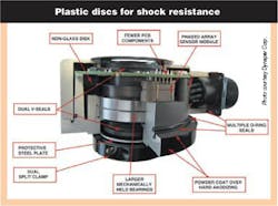
The code discs (also called wheels) on rotary optical encoders consist of etched metal, Mylar, emulsion on tempered glass, or chrome on glass. The latter gives superior edge definition, immunity to condensation, and durability, though is susceptible to scratching and fracture under shock. Plastic discs are shock resistant, but some can warp at higher temperatures. Metal discs withstand shock, heat, and chemicals, though can exhibit less accuracy than glass varieties.
Unique threats to optics-based encoders are particulate and liquid contamination. In outdoor and washdown applications, liquid ingress occurs when encoders are directly exposed to hot, pressurized water, coolants, lubricants, and cleaning agents. Ambient temperature variations can also accelerate encoder failure rates. During encoder cool down, pressure differences between the outside environment and housing interior can draw air into the latter. As the encoder’s housing temperature drops, contained humidity condenses inside, collecting dew on code disc, printed circuit boards, and wiring — and heightening odds of failure. Finally, without ruggedized sealing, sand, salt, small wood chips, or dust particles can invade standard encoders, blocking optical processes and degrading performance.
Rotary magnetic encoders
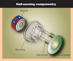
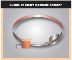
Magnetic encoders are inherently rugged and operate reliably under shock and vibration and high temperature. Magnetic debris ingress can degrade rotary magnetic encoder performance, but other contaminants do not. Therefore, rotary magnetic encoders are often used instead of optical encoders. Passive variable reluctance or magnetized strips on a rotating code rotor, wheel, or band are sensed by either a Hall-effect or magnetoresistive sensor. Motor speed and position accuracy dictate which of the two is better suited for an application.
Rotary magnetic encoders can take the form of small, inexpensive devices used in high-volume applications, such as vehicle antilock braking systems, or sophisticated units demanding motion control tasks, such as industrial automation systems and medical equipment. Available variations are incremental and absolute types; non-contact and bearing versions; and units in which rotating unit and encoder body are effectively separate subcomponents.
To illustrate, a 15-mm encoder contains a 7.6-mm-diameter wheel, magnetized with 32 poles (16 north and 16 south) using a static fixture. Fixture size typically limits the number of poles that can be embedded. The pole pitch for a 32-pole motor is about 0.75 mm, the smallest practical size a fixture can handle.
Consider a common setup using a target magnet disc plus three digital Hall-effect sensors (120° electrical apart) on a circuit that pick up commutation signals from the wheel. The Hall effect sensors turn switch when north and south poles pass.
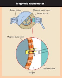
Hall-effect encoders usually switch with an output characterized by hysteresis — when the magnetic field from the rotating encoder wheel reaches a flux density sufficient to overcome a critical threshold level. Likewise, when the detected field reaches a flux density below a lower threshold level, it switches back to the previous state. Consequently, Hall sensors containing 32-pole encoder wheels generate 16 pulses per revolution.
It’s not only commonly sized encoders leveraging this type of operation. Some miniature single-magnet system-on-chip designs integrate field-sensing Hall elements and digital signal processing for simultaneous absolute, incremental, and pulse-width-modulated digital outputs. A small, diametrically polarized magnet rotates above an ASIC; the latter contains an array of Hall effect sensors that detects magnetic flux changes and generates a voltage as the magnet rotates above it.
Today, however, higher resolution is needed from miniature and high-end encoders — a need increasingly met by encoders using magnetoresistive material that lowers bulk resistance by about 1.6% in the presence of a saturating magnetic field. Magnetoresistive sensors differ from Hall-effect sensors in two important ways. First, the saturating field is in the range of 0.003 to 0.005 T, an order of magnitude smaller than typical switching fields for digital Hall sensors. This makes magnetoresistors more sensitive measuring devices. Second, the change in resistance is independent of magnetic field polarity, so the 32-pole wheel generates 32 pulses per revolution, twice the resolution of previous sensors.
A magnetoresistive sensor assembly comprises an array of thin nickel-iron permalloy strips.
Strip width is much larger than thickness. The sensor is located above the magnetic track of the encoder wheel with the strips parallel to the wheel axis.
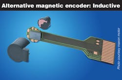

One channel of a magnetoresistive sensor consists of two strips displaced one-half pole pitch from each other. They are connected differentially to double the sensor's output voltage. As the encoder wheel rotates past one pole (two sensor strips), the output voltage completes one cycle, generating a 40-mV peak-to-peak signal from a 5-Vdc power supply.
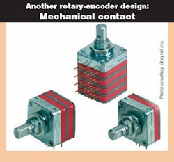
Encoder bearings and mounting options
Most (though certainly not all) optical and magnetic encoders are supported by bearings that allow the shaft to turn while permitting the encoder housing (often enclosing sensor electronics and in some cases, code disc or wheel) to remain immobile. These bearings are not designed to support high loads, and should not be exposed to extreme shock, vibration, full system load, or that arising from misalignment. The relationship between bearing loading and life is:
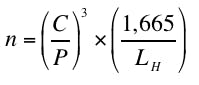
Where n = Bearing life, revolutions • C = Dynamic capacity (from manufacturer’s data) • P = Bearing load, lb • LH = Design life of bearing, hours. Bearing life is approximately inversely proportional to the third power of the load. Bearing assemblies can be built with tolerances that allow their use at higher speeds, to 30,000 rpm. However, if the encoder is hard-mounted to the motor shaft and the encoder housing is hard-mounted to a base plate, the bearing assemblies could experience side loads of several hundred pounds.
Standard encoders incorporate their own shaft and bearing assembly. In very low-cost or miniature encoders, sometimes adhesive secures bearings to the shaft hub, though vibration can cause failure here. More commonly, the encoder shaft couples to the motor shaft with a belt, gear train, or coupling. For the latter, perfect alignment of encoder and driving shaft centers of rotation is impossible, so flexible couplings are often used. Manufacturers offer detailed guidelines on proper mounting.
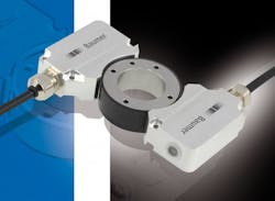
In contrast, hollow-bore (also called hollow-shaft) encoders slide over and clamp onto a precision shaft, attaching directly to the motor frame through a flexible mount. A proper fit between the bore and shaft plus a good flex mount help retain accuracy and extend encoder bearing life.
Both standard and hollow-shaft encoders are known for being rugged.
The terms modular and kit in reference to rotary encoders mean different things depending on the manufacturer, but in both, locking fittings fix the disc or wheel to the shaft. Sensitivity to motor shaft run-out and axial movement can be issues, and on optical encoders, significant play can push the disc into the optics. Other modular encoders are fully contained, self-protecting shielded kits that mount to motor shafts.
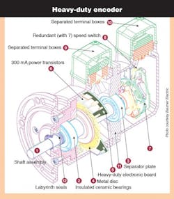
In recent years, many manufacturers have increased the sizes of their encoder bearings, to carry more load and last longer. In certain cases, such bearings are fitted on opposite sides of a solid housing surrounding sensor electronics to make for a slightly bulkier design, but one exhibiting a durable shaft preload condition that can withstand significant radial and axial loads, shocks to 500 g, and -40 to +100° C.
Elsewhere, ceramic ball bearings (for isolation between the housing and encoder shaft) prevent shaft-current buildup from ac motors and generators — of particular concern on VFD-driven designs. Otherwise, unblocked stray or parasitic shaft currents through an earthed encoder housing to the ground cause electrical discharge machining (and failure) of bearing rollers and races.
Note that even ABEC 7 bearings have rolling errors of 22 arc-sec or so. Encoder resolutions exceeding 50,000 counts per turn reflect this bearing noise in the form of position error. Thermal mismatches between mating components in the bearing assembly can also degrade performance and expected life.
Die-cast housings on certain heavy-duty encoders allows the length of the shaft to be extended between bearings, allowing the mounting of a second encoder or mechanical centrifugal switch. This device triggers an action when a specific speed limit is exceeded; electronically independent of the first system, it provides redundancy in applications requiring extreme safety.
Note that if the encoder protrudes into a high-traffic area it may be subject to damage, such as from a hammer or forklift vehicle; if situated near floor level, an encoder can be perceived as a useful step. Here, a cage or shield may provide acceptable protection.
Encoder sealing and environmental protection
For designs that incorporate bearings, perfectly sealed encoders are impossible, as there must be clearance to allow the bearing to slide over the shaft during encoder assembly. Even high-IP-rated bearings with rubber or plastic lip seals cannot cover all rotational speeds, designs, and mounting positions — and all seals are subject to wear, aging, and UV radiation degradation.
Encoder bearings can be open (least protection), shielded (moderate protection) or sealed (most protection). With all but totally sealed encoders (often associated with magnetic types) shaft-up encoder orientation is least preferred. That said, some hermetically sealed encoders (to IP67) can be installed in various directions, indefinitely submerged in liquids, or pressure washed to 12 bars and 100 liters/min. Labyrinth seals with reverse-lead spiral grooves prevent the ingress of liquids and particulates into the housing. However, shaft seals can be a source of heat generation, so designers must verify limits with the manufacturer.
Final notes on resolution and accurate output
When specifying encoder resolution, error analysis is a consideration. It’s good practice to choose an encoder that will read two to four times better resolution than the machinery’s maximum error source. Resolution and bandwidth are related:
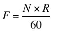
Where F = Frequency, Hz • N = speed, rpm • R = Resolution, counts per turn. System operating speed is usually known or dictated by tradeoffs such as system throughput versus scrap rates. Inherent errors in a system will limit resolution.
Using charts or manufacturer input, engineers can determine the operating bandwidth of the system. It’s dictated by the type of output driver (line driver, open collector, or push-pull hybrid), cable length and type, and controller-end terminations.
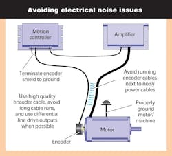
Consisting of two transistors with collectors connected, line drivers ensure low-impedance output. Because of their low impedance, they exhibit good noise immunity and can be used with cable lengths to 1,000 ft and operating frequencies to 1 MHz. However, their high switching speeds makes for ringing. Signals for these outputs should be specified to include the channel complements and be carried in shielded, twisted pairs — and fed to a high impedance differential-line receiver, or opto-isolator, which offers common mode noise rejection.
Due to their higher impedance, open collectors are more bandwidth limited. A good rule of thumb is to use them at a maximum of 50 kHz with a maximum of 50 ft of cable. They are the least expensive type of output. Note that the pull-up resistors can be user supplied or factory installed within the encoder, or both. The arrangement is often dictated by the controller or the need to operate the encoder at a different voltage than the supply voltage.
Encoder output data is sent to the controller via parallel binary, analog voltage or current, Profinet, Ethernet Powerlink, EtherNet/IP, Modbus, DeviceNet, Profibus, CANopen, or other networks. For example, Standard Serial Output (SSO) is typically leveraged in magnetic-encoder designs, allowing continuous synchronization during data transmission.
Another option is the Synchronous Serial Interface (SSI), a digital point-to-point interface. Common in Europe, it provides unidirectional communication to 1.5-MHz speeds and uses a six-wire cable — two carrying clock data to the encoder, two carrying data from it, and two wires for power. Finally, hardware compatible with SSI, connectable via a bus or point-to-point, Bidirectional Synchronous Serial interface (BiSS) is an open protocol that transmits encoder position data whenever the controller asks, allowing for quick recovery after interruptions. It also communicates encoder identification information, and acceleration, temperature, and other data without interfering with realtime operation.
Note: A system’s controller generally dictates encoder output — so designers should first determine the controller's input requirements, and then select a compatible encoder output driver. The three basic types are drivers that supply current to external devices (sourcing); drivers that provide a current path to the circuit ground or common (sink); and drivers that do both (line drivers). Many controllers accept differential line-driver signals, canceling common-mode noise while accommodating long cable runs.
To ensure reliability, the power supply to the encoder should be filtered and regulated; power lines for other devices should be routed away from encoder cabling. In some cases, specially coated terminal boxes shield against electromagnetic compatibility fields to prevent signal output failure. Encoders designed with such boxes can be rotated through 180° to position the cable opening to the left or the right of the encoder (to facilitate installation.) In all cases, shielded twisted pairs of cable are required, and the ground properly connected — preferably in star arrangement — to ensure effective shielding.
About the Author
Elisabeth Eitel
Elisabeth Eitel was a Senior Editor at Machine Design magazine until 2014. She has a B.S. in Mechanical Engineering from Fenn College at Cleveland State University.
Voice Your Opinion!
To join the conversation, and become an exclusive member of Machine Design, create an account today!

Leaders relevant to this article: