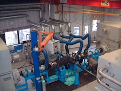
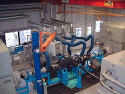
Measuring torque, rotational speed, angle of rotation, and the quantities derived from these variables are increasingly critical in the design of new test benches for use in industrial environments. When selecting and designing these benches, higher requirements for accuracy and speed, automation, and efficient operation must be considered.
Important factors that influence the components in a successful test bench design:
· Requirements of innovative test benches
· How to design torque sensors
· How to enhance the performance of torque measurements
· Performance features data acquisition and automation systems should have
· Using PC-based data acquisition systems or embedded control systems for measurements
· Features for onsite or remote service concepts
Requirements of innovative test benches
Industries where energy efficiency is important, such as the automotive and aviation industries, are increasing focus on engine development, rolling resistance and energy-conversion efficiency. For example, the development of standards for the next phase of more fuel-efficient vehicles—particularly medium-to-heavy duty fleets in the automotive industry—is one critical application for innovative test benches. The right bench design will help ensure vehicles are properly calibrated that will bolster energy, security, and cut carbon pollution, thereby saving money and supporting manufacturing innovation. As such, engine manufacturers and drivetrain engineers have a challenge: to enhance the performance of current and future engines with fuel efficiencies to comply with efficiency standards, such as EURO-Standard 5, while remaining competitive and satisfying customer expectations.
For today’s manufacturers to be successful, they must be ready to quickly respond to market needs with new yet mature products. The need for speed means they must have shorter development times and test methods that are efficient and flexible. This in turn requires separating the preparation of the test job from operating the test on a single engine.
Manufacturers have the opportunity to improve testing by implementing structures quickly. Intelligent sensors and measuring amplifier systems can improve efficiency by communicating and exchanging configuration data by using Transducer Electronic Data Sheet (TEDS) sensor data detection.
Essential preconditions for quick test implementation are high-quality measured values and accurate measurement. In addition, the measuring amplifier and control system must be capable of further processing the measurement data in real time so that the test bench can be regulated. It is also essential to capture measurement data at a high resolution for analysis and to save it.
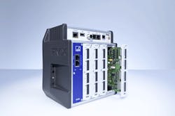
To achieve better gains in a test bench, all the aforementioned functions should be available in a single device—which allows for more efficient use in testing and proving grounds as well as for measurement and automation in the production area.
By combining flexible hardware with data recording at the highest data rate and resolution, users can experience up to 10 times the time and cost savings.
How to design torque sensors
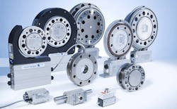
Modern torque transducers must work with digitized data and at high sampling rates to meet the high requirements of the function tests. Available output signals include not only torque but also rotational speed and angle of rotation. These measurements are important to calculating power and energy conversion efficiency.
Measurement signals should be converted into frequency signals to ensure noise-free transmission. This approach is indispensable for harsh ambient conditions frequently encountered, as even larger engines or frequency inverters must not adversely affect measurement quality with their electromagnetic fields.
The most important metrological properties of torque sensors include: Accuracy class, sensitivity, tolerance, temperature stability, linearity deviation and hysteresis. The user should also note the application areas and load limits, including: Rotational speed limits, permissible oscillation bandwidths, lateral limit and longitudinal forces, maximum temperatures.
How to enhance the performance of torque measurements
To optimize torque data, a measuring amplifier system must include a series of internal computing channels specifically designed for operation and use of torque transducers.
♦ A 21-point linearization of the characteristic curve of the transducer for the torque sensor improves the raw signal, which can then be further processed to increase the measurement quality of the test bench.
♦ Polynomials and straight pitches—especially with the use of polynomical-scaling—can increase efficiency because they represent the sensor characteristic with greater accuracy. Using the polynomials for sensor adjustment is more accurate than two-point scaling or a characteristic table.
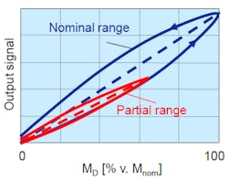
♦ Calibration equipment can capture the behavior of the sensor to increase its accessible accuracy under various load cases, which include dynamic right and left rotation as well as highly accurate measurement in partial ranges. The ability to measure partial ranges is necessary to capture the residual breaking torque, in which different applications are measured during the calibration of the sensor. The breaking torque determines the corresponding characteristic curves according to standards DIN51309 or VDI/VDE 2646 and is held firmly in the calibration protocol which is part of the delivery of the torque sensor. These characteristics can then be stored within the amplifier settings and used in the application. From the current measured values from the torque sensor, the amplifier would recognize in which application the torque sensor is present and automatically share the predefined sensor characteristics. This is very useful because the measuring error can be reduced, especially if the sensor is calibrated and used also in a partial measuring range.
♦ Parallel, independent processing of raw measurement values, such as filtering, makes it possible to adapt the signals for regulation and automation of the test bench. The combination of analog outputs and/or real-time Ethernet fieldbuses enables users to implement efficient test bench automation.
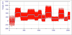
♦ A special filter for testing is also critical for measurement of combustion engines. Due to the work cycle with compression and expansion in the individual cylinders and the corresponding fluctuations in combustion, the torque generated by an engine exhibits highly dynamic behavior. In many measurement systems, it appears falsely as "noise" (or rapid changes). This can be eliminated using a Center for Advanced Studies in Measurement and Assessment (CASMA) filter (a filter that works angle-synchronously).
♦ Determining peak values or mean values of measurement signals can document test limits. These control values can be monitored in turn with limit values or tolerance bands in real time, making it possible to control the test bench.
♦ Mathematical computing channels can calculate and output the application of torque in real time if the raw values of the torque measurement with torque and speed are available. Connectible timing elements can correct additional runtime differences in the measurement signals. These differences occur in high-performance load cases on the transducer side and can have negative effects on measurement results.
♦ Test signals simulate signals and system states as well as test functional capability during startup. This is possible without having to place the test bench completely in operation and can be done on the sensor side by activating a simulated sensor called a shunt signal. Then the torque transducer emits 50 percent of its nominal (rated) signal and the function is tested in a dry run.
Performance features, data acquisition, and automation systems should have measurement signals to acquire an extensive range of data (e.g. 30-100 data signals on a test bench). It includes simple signals, acquired at a low frequency about 30 Hz to 20 Hz (a slowly changing temperature value, for example). It also includes complex measurement data that has to be simultaneously measured at a high frequency up to 3 MHz, such as torque signals with angle of rotation signals and rotational speeds that must be acquired synchronously. Decisive factors here include not only sturdy and accurate sensors but also robust and accurate measurement acquisition. The sensor and amplifier should be in the same accuracy class and should be at least 0.1%, or preferably at 0.01%. However, up to 0.01% is possible for some high application that requires higher accuracy.
The sampling rate of the signals is just as important as measurement accuracy. It should be high enough so that fast or small partial changes can still be reliably resolved and displayed. To cover acquisition of peak values, computing speed, and regulating quality, all measuring and computing channels must be sampled in parallel at a rate of at least 20 kHz, which is equivalent to a measuring and calculating grid of 50 microseconds.
Using PC-based data acquisition systems or embedded control systems for measurements
There is a basic distinction between PC-based data acquisition systems and embedded control systems within the measurement system. This applies to acquisition of measurement data, control, regulation and visualization. If regulation requires high real-time deterministics, embedded systems are a better choice because data, while quite small, is also time critical.
Regulation in real-time cannot be implemented on PC-based systems. Because resources are distributed uniformly over all components of the PC, control tasks are not processed in real time and must wait in some cases before they can be executed. The cycle times are therefore 50 ms or more, which is not adequate for fast and reliable test bench regulation. Soft PLCs are PC capable of regulation in real time, however, this is not common.
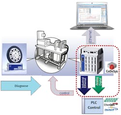
However, embedded systems reserve their resources entirely for regulation tasks through the internal central processing unit. The same is true for soft programmable logic control (PLC) solutions integrated into measurement systems. An amplifier system equipped with a CODESYS soft PLC can control the entire test sequence.
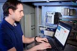
Compared to PC-software based solutions in the past, visualization systems are more in demand today with new, web-based technologies. They only need a web browser to be available on all modern terminal devices, including PCs, tablets and smart phones. No additional software must be installed on the terminal device. There is always a browser present. The mobility and availability of these devices are convenient not only to users but also to maintenance personnel.
Data storage
If only the end results of the test will be logged or stored, the measurement device can have an embedded acquisition system. PC systems are able to store larger amounts of data due to bulk storage options. In this case, data acquisition software can record the data on a PC in parallel to measurement and control operation. The bandwidth includes ready-to-use standard software prepared in advance for these types of tasks as well as special solutions which accomplish these tasks by means of software drivers and application programming interfaces.
PC systems can easily save documentation of test results individually and, if necessary, send them to a printer. However, the trend is to use database-oriented documentation with the results and transfer measurement data to large archive databases. Then the required reports can be generated through queries and statements describing status or capacity utilization. The quality of components can also be generated.
Features for onsite or remote service concepts
Service requirements may be categorized as either onsite service or remote service. Measurement and control systems must actively support personnel on site during startup and maintenance. This means it must be possible to query the status of measured values and the device and obtain the desired information directly—either as an LED display on the device or by using a menu in the web browser.
Log files make it easy to record and query all errors and details of device operation. This is especially helpful when searching for sporadic errors or effects. Another possibility for querying is to make monitoring signals available. These are voltage signals to which the measurement signals or the computing channels can be interconnected for monitoring purposes. Then a simple measurement can be conducted onsite by any service engineer. The log files are stored as power failsafe in the device and can also be downloaded and archived via a web browser for documentation purposes.
The general trend observed here is that conventional measurement technology systems and automation solutions are moving ever closer together. Modern and powerful torque sensors combined with embedded systems featuring open communication interfaces are suitable for high-quality measurement and regulation tasks. In addition to controlling the measurement sequences themselves, this type of modern system can also control machines and implement modern, forward-looking test benches.
