Noise Prediction for Moving Mechanisms Using Coupled MBD-Acoustics Analysis
Reducing the time and resources needed to design quality products is a constant industrial challenge. Integrating different computer aided engineering (CAE) tools is one way to help engineers streamline the process.
For example, giving engineers using Multi-body Dynamics (MBD) software access to acoustic data lets them detect unsatisfactory designs without the direct support of acoustic engineers. Combining multi-body dynamics and acoustics data into a single simulation gives MBD engineers an insight into the acoustic behavior of moving mechanisms early on in the design process.
Multi-Body Dynamics Coupled with Acoustic Analysis
It is generally difficult to predict the noises coming from moving systems such as transmissions and gearboxes. Complicated moving mechanisms inside the system and different ways in which the parts interact and cause varying contact forces and vibrations. Also, understanding how the dynamic performance can influence the acoustic waves radiated from the gearbox casing is also a big challenge.
Without the ability to accurately predict how the system dynamics will impact its noise performance, engineers do not have an efficient method to redesign their systems to improve acoustic behavior.

The traditional workflow for such analysis involves three interfaces, a multi-body dynamics (MBD) tool, a finite element analysis (FEA) tool, and acoustic software. First, engineers need to perform the dynamic analysis in an MBD tool to get the dynamic loading on the gear casing surface, and since those time-domain results usually cannot be read into acoustic software directly, they would need to convert the complete structure response in the frequency domain. After that, they can finally read the surface vibration into the acoustic software and use it as a boundary condition. This workflow is fairly laborious and could require several computer aided engineers to handle a change in the design.
A new methodology recently developed lets the engineers perform the modeling within the MBD interface and get initial results and impressions of the acoustic behavior without manually exporting the results into acoustics software to perform noise analysis. Typical acoustic results are computed via an acoustics solver, and displayed in MBD interface, including the acoustic pressure evolution in time at selected positions around the model and audible wave files for listening to the sound.
Such new workflow greatly reduces the time and cost to conduct acoustic analysis on moving mechanisms like a gearbox, letting engineers do more iterations in the same time compared to conventional methods. Indeed, the new methodology fully automates this workflow into a single simulation environment by embedding a time domain acoustic analysis into an MBD tool. This allows MBD engineers to perform a first iteration on acoustic results including the evaluation of the sound quality provided by a specific product design. Thereafter, and only if deemed necessary, acoustic engineers can perform a more detailed analysis by investigating acoustic maps in the time domain or by converting only the most relevant results in the frequency domain.

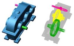
Consider a gear box example. The motion of the gearwheels causes gearbox vibrations which then affect the physical behavior of the gearwheels, leading to a strongly coupled problem. The vibrating gearbox also transmits energy to the surrounding fluid and the acoustic waves radiate from it. Acoustic waves affect the structural vibration as well. However, assume that the multi-body dynamics and structural simulation domains are usually strongly coupled and should be solved simultaneously. Also assume that the feedback from the acoustic waves to the structure can be neglected when considering an acoustic radiation in air. These assumptions let engineers split the analysis of a vibrating structure into two subsequent steps. The MBD analysis is run first and outputs the structural vibration on the structural domain. These vibrations are then used as a boundary condition for the acoustic analysis which can be efficiently performed by means of a time-domain FEM solver especially for transient phenomena. These two steps can now be easily integrated into a single MBD simulation environment.
Once simulations are completed, the acoustic pressure at microphones surrounding the virtual prototypes is outputted. The outputs time domain series can be easily converted in to audio files to listen to the response of the prototype to a certain excitation. The time domain data can be further post-processed in the frequency domain by means of spectrograms which show multiple signal spectra allowing the display of noise levels evolution with respect to the working regimes. These types of waterfall diagrams are useful especially for analyzing sound and vibration signals from rotating and reciprocating machinery as they allow performing an engine order analysis. Frequencies that correspond to the motor’s revolutions per minute (RPM) or multiples of it are called orders. The first order is identical to the frequency of the RPM; the second order is the first multiple and so on. An order analysis allows the determination of the signal level for each specific order. Its importance in the field of rotating and reciprocating machinery is due to the fact that these machines have a variety of parts impacting uniquely the whole sound and vibration response. With an order analysis it is possible to identify each contribution to analyze the performance of each single part.
The Gearbox Example
Consider a gearbox composed by three gear pairs. The input wheel is subject to a rotation ranging between 0 and 3000 RPMs. To evaluate the acoustic response we can consider a number of microphones distributed around the gearbox. For example, the microphones could be spatially distributed accordingly to the standard ISO 3744.
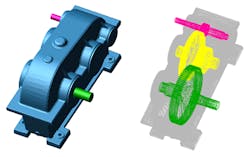
In the MBD model, the gearbox casing is considered flexible to capture its surface response. The rest of the gearbox (i.e., gears, shafts, bearings) are rigid parts. Although the gears are not flexible parts, it is still possible to calculate the tip relief and crowning effects which can impact the dynamic loading on the gearbox casing.
After the MBD model is set up, a 5-second dynamic analysis was conducted with the rotational speed of the input shaft ramping up from 0 to 3000 RPMs providing outputs for all the loads and contact forces of each component as well as the displacement, velocity and acceleration of each system’s part.
Following the MBD simulation, and while still in the MBD environment, an acoustic toolkit was launched to set up the parameters for the acoustic analysis like the acoustic mesh, radius of the infinite elements, speed of the sound, fluid density, output format, acoustic environment (the material) and other parameters.
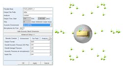
What the toolkit does is convert the MBD results into boundary conditions for the acoustic model, and performs the acoustic analysis in the background using the acoustic solver. Specifically, the casing acceleration (or equivalently the displacement or the velocity) and the surface mesh of the casing are used to feed the acoustic simulation tool. As the meshing requirements for the structure model are more restrictive than the acoustic ones, the structural and acoustic meshes are incompatible. This also implies that a projection procedure from the structural mesh to the acoustic one is needed. When the acoustic simulation is done in the MBD environment, you can go to the MBD post-processor and get some of the acoustic results of this gearbox casing like the acoustic pressure evolution in time for the surrounding microphones at each microphone location and sound file.
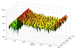
Figure 5 shows an example of the acoustic response in time domain of all the surrounding microphones. The first result allows the identification of areas where the acoustic pressure could exceed unwanted values resulting in potential noise issues. The data can be converted in audio files to get the audio quality of a certain gearbox design directly in a single simulation environment, enabling MBD engineers to detect unsatisfying results from an acoustic perspective.
Time domain data can be further post-processed in the frequency domain to get a thorough understanding of the acoustics. For example, Fig. 6 depicts the spectrogram of the noise at a microphone surrounding the gearbox case. The main noise contribution is given by the 25th and 50th orders highlighted by two straight lines in the picture. These orders are linked to the first gearwheel since it features 25 teeth. Between 800 and 1300 Hz the noise levels are much higher. This is due to the excitation of specific structural modes by the first gearwheel.

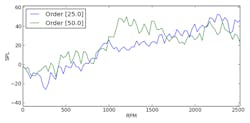
Figure 7 depicts the Sound Pressure Level (SPL) versus the machine RPM extracted from the plot of 6. This allows better understanding of the impact of the different orders on the acoustic performance. Indeed, at low machine rotational speed the 50th order has a major contribution to the radiated noise, whereas the 25th mainly impacts the system at higher rotational speed.
Conclusions
Advances in the integration of CAE technologies help reduce time and resources. This article illustrates how the integration of multi-body dynamics and acoustics can change the workflow for the engineers. Specifically, multi-body dynamic and acoustic time domain analyses can be integrated into a single simulation environment allowing MBD engineers to perform preliminary acoustic performance evaluations of their products. This includes the investigation of the noise quality via the generation of audio files, and providing advanced acoustic results that can be further post-processed by acoustic engineers to better understand the noise performance of a product.
Dr. Diego Copiello is a Product Marketing Manager for Free Field Technologies, developers of Actran acoustic simulation software and an MSC Software Company; Yijun Fan is a Product Marketing Manager at MSC Soft9ware for Adams & Easy5.
About the Author
Voice Your Opinion!
To join the conversation, and become an exclusive member of Machine Design, create an account today!

Leaders relevant to this article: