How to Select and Size Hydraulic-Oil Coolers
This file type includes high-resolution graphics and schematics when applicable.
Heat kills hydraulic systems. That’s why hydraulic oil coolers are widely used in a diverse range of agricultural, mobile, manufacturing, and industrial settings. They remove excess heat generated by energy losses in a system, as well as that from external sources such as engines, furnaces, and even the surrounding environment.
In fact, coolers are often essential for designing temperature-optimized hydraulic systems that keep oil temperatures within a limited range. Such circuits are basic prerequisites for cost-efficient operation, as they provide a number of performance, economic, and environmental benefits. These include:
- Maintaining the correct temperature keeps oil at its recommended viscosity, ensuring mechanical components are properly lubricated and hydraulic devices run at peak efficiency. Letting oil temperature rise beyond recommended limits can reduce the life of a system due to poor lubrication, higher internal leakage, a higher risk of cavitation, and damaged components.
- Keeping temperatures down also helps ensure the oil and other components last longer. Excess heat can degrade hydraulic oil, form harmful varnish on component surfaces, and deteriorate rubber and elastomeric seals.
- Operating within recommended temperature ranges increases a hydraulic system’s availability and efficiency, improving equipment productivity.
- Finally, with more machine uptime and fewer shutdowns, it reduces service and repair costs.
Considering the benefits coolers offer, it’s apparent that accurately sizing them is a paramount concern for design engineers. Undersizing obviously allows higher-than-recommended oil temperatures. But oversizing hurts system efficiency as well, by reducing temperatures below the recommended range and increasing costs with a larger-than-necessary purchase. Here are some tips on selecting the right type and size cooler for a specific application.
Cooler options
Several different types of coolers are suitable for hydraulic systems, with air and water cooled being the most common.
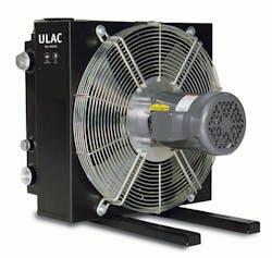
Air-cooled systems dissipate heat with flowing air. This type of cooler operates by forcing cold air over hot fluid inside a heat exchanger’s coil or core. Low running cost and simple maintenance are attractive benefits of air-cooled systems. They also eliminate water-contamination problems and minimize corrosion. Additionally, heat generated from air-cooled systems can be used for other purposes.
On the downside, the upfront expense of an air-cooled system exceeds that of a water-cooled unit. Air-based versions are also larger and generate more noise, so they can degrade the work environment. What’s more, these coolers require ventilation and clean air, and variations in ambient temperature can greatly affect cooling capacity — making steady-state operation more difficult to maintain.
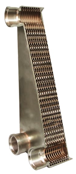
Water-cooled systems use cold water to remove heat, with hot and cold fluids separated by a barrier. Compared to air-cooled systems of equivalent capacity, water-cooled systems have lower up-front costs. They’re also quiet, compact, and do not alter the surrounding ambient temperature. Variations in air temperature have little or no effect on cooling capacity, which allows for greater consistency. Meanwhile, the system’s heated water can be used for other on-site purposes.
Although water-cooled coolers cost less, they generally require clean water. Continuously running water can be expensive, leading to higher operating costs. Other concerns include risk of corrosion and erosion, and increased maintenance. Water-cooled units can also freeze in cold weather, letting water contaminate the oil.
Other cooler types include refrigerated chillers and evaporative cooling towers. In all instances, engineers should first choose the most appropriate type, and then size the unit for the specific application.
Application data
After selecting the type of cooler, the next step is assembling pertinent application data such as maximum system temperature, type of fluid to be cooled, fluid-flow rate, maximum allowable pressure drop of the cooled fluid, and the heat load.
Determining heat load is essential. Many users assume an efficiency for their system, and then derive the heat load. For example, if operating under the premise that a system is 70% efficient, one can assume the remaining 30% of input power is the heat load. Estimating an overall system efficiency produces a heat load figure, but calculating heat load is generally more accurate.
One analytical method involves measuring all pressure losses and flow rates in the system, which, in most cases, is not practical. Another, simpler method measures reservoir temperature over a given period of time. By monitoring reservoir temperature and knowing the type and volume of fluid, heat load, Q, can be calculated using:
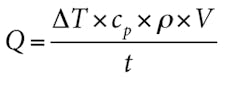
where âT = rise in temperature; cp = specific heat; ρ = fluid density; V = total fluid volume, and t = time.
The more accurate the system data, the better one can gauge required cooler size. After calculating heat load, engineers may apply a correction or “safety” factor to account for uncertainties. Whether or not to use one depends upon how conservative the design needs to be and the level of confidence in the data. More likely, engineers inadvertently apply a safety factor when determining the cooling-fluid temperature (the ambient air temperature for air-cooled oil coolers or water temperature for water-cooled oil coolers). That is, calculations often use an ambient air temperature of 100°F or higher, and water temperature is often set at or above 80°F. In reality, fluid temperatures are rarely this high.
Another consideration is whether the cooler will be plumbed in the return line or in an off-line recirculation loop. It can make a big difference. Sizing coolers installed in return lines is rather straightforward. Coolers can either be sized using maximum system temperatures or maximum reservoir temperatures. Oil temperature entering the cooler is the system temperature, and oil temperature exiting the cooler is the reservoir temperature.Sizing off-line coolers can be much more complicated, depending on pump inlet location in relation to the return-line outlet, and whether or not there are any baffles between the two. In a worst-case scenario, the cooler is sized such that inlet temperature to the cooler matches the required reservoir temperature. This means oil exiting the cooler is colder than the desired reservoir temperature. But this cold oil mixes with hot return-line oil that has not been cooled at all. Mixing the two sources of oil, along with the locations of the oil lines relative to each other, complicates modeling of actual reservoir conditions.
Additional factors
In addition to the above considerations, other application factors are also important. When opting for air-cooled hardware, be aware of altitude, maximum ambient air temperature, and the type of motor driving the fan. Ac, dc, and hydraulic motors are all suitable.
On the surface, the type of motor may seem of little consequence to an oil cooler’s capacity, as long as a motor provides the necessary power to drive the fan. But motor type can affect the size of a cooler. Typically 12 and 24-Vdc fan motors do not have the power density of ac motors. That means dc fan drives cannot push or pull as much air across a core as can ac drives. Because less air crosses the core, cooling capacity is lower as well. As a result, a dc fan drive may require a larger cooling package than would an ac drive.
With water-cooled coolers, first determine the type of water the unit will use — fresh, salt, or water/glycol mixture. If opting for water/glycol, it is important to clarify the type of glycol as well as the water-to-glycol ratio. Also determine the maximum water flow rate and maximum allowable waterside pressure drop. These figures are not always obtainable, but they help improve cooler selection.
SelectIng a cooler
Given the necessary data, engineers can then turn to sizing. Coolers can be sized using software programs or by interpolating graphs, both of which are available from cooler manufacturers. Software offers the simplest and quickest solution. Users need only enter the recorded data into the proper fields, letting the software calculate the optimal size.
For example, Parker has an air-cooled cooler sizing program that engineers can download at http://tinyurl.com/mf5nv73. Inputs for this program include the type of oil and flow rate, inlet and ambient temperatures, heat load, and altitude. Outputs include inlet and outlet oil and air temperatures, specific heat dissipation, oil pressure drop, and noise level.
The program can select a cooler based on input data, or the user can pick a certain cooler and analyze its capability. However, a software program is only as “intelligent” as the data it receives. For this reason, knowing how to interpolate graphs can help engineers better understand cooler sizing and selection.
Graphical sizing
The heat-rejection capacity of a cooler varies based on the type of fluid, fluid flow rate, difference between the two fluid temperatures, and other factors. Graphs typically express heat load versus fluid flow rate at a given set of conditions.
Graphs are based on either entering temperature difference (ETD) or approach temperature. ETD refers to the temperature of the hot fluid entering the cooler minus the temperature of cold fluid (water or ambient air, depending on the cooler type) entering the cooler. ETD curves present data on a “per degree” basis or a nominal temperature difference, typically 50 or 100°F. This means, for example, that a 50°F ETD is the result of 150°F hot-fluid temperature minus 100°F cold-fluid temperature.
Approach temperature refers to the temperature of the hot fluid at the cooler’s outlet minus the temperature of the cold fluid entering the cooler. Approach temperature curves are generally based on an approach temperature of 40°F.
To simplify, ETD looks at the temperature difference prior to the cooling process; whereas, approach temperature uses the final temperature attained through cooling.
Graphs may require users to convert units of measure to match a graph’s units for heat load and flow rate. Common units of measure for heat load include:
- Btu/hr°F ETD.
- Btu/hr @ 100°F ETD.
- Horsepower @ 40°F approach temperature.
Correction factors
Often when interpolating graphs, engineers must apply correction factors for parameters like oil viscosity, altitude (for air-cooled), motor frequency (for air-cooled with ac motor) and oil-to-water ratio (for water-cooled without individual curves for various oil-to-water ratios). There may be safety factors to consider as well.
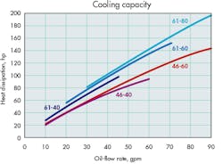
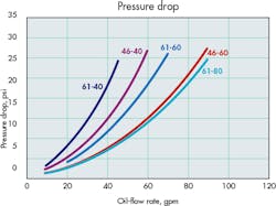
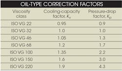
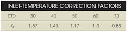
For example, graphs on page 36 show cooling capacity and pressure drop for Parker OAW water-type coolers. The cooling curves are based on specific conditions. These include ISO VG 32 oil, an oil/water ratio of 2:1, and an oil/water inlet difference of 60°F. For other conditions, engineers must use the following correction factors.
Correction factors for other oil types.
Cooling capacity: Multiply the desired cooling capacity by correction factor Kv.
Oil-pressure drop: Multiply pressure drop by correction factor Kp.
Correction factors for other inlet temperature differences.
Cooling capacity: For inlet-temperature differences other than 60°F, multiply the desired cooling capacity by correction factor Kt.
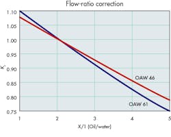
Correction curves for other oil/water flow ratios.
Cooling capacity: For oil/water flow ratios other than 2:1, divide the desired cooling capacity by factor Kr obtained from the curves in the Flow ratio correction graph.
Graph navigation
After making the proper conversions and adjustments, follow these steps to select a cooler:
• Find the flow rate along the X axis of the graph that corresponds with the recorded flow rate.
• Move up from this flow rate until the Y-axis value matches the calculated heat load.
• Select the curve that intersects at this point. If there is no curve at the point of intersection, use the closest curve above the intersection.
• The curve indicates the correct cooler size.
(See the accompanying sidebar, Sizing a cooler, for a step-by-step sizing example.)
Knowing the correct cooler size, users can customize base models to a certain extent. Air-cooled products, for example, may come with several different types of motors and voltages. In addition, users can often specify options like temperature-control switches, and pressure and temperature bypass valves. Water-cooled units may include options for the number of passes, baffle spacing, and cooling-tube size.
Sizing a cooler
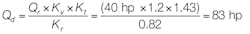
Here’s a quick look at sizing a water-cooled hydraulic oil cooler, in this case a Parker type OAW cooler. Operating conditions include: ISO VG 68 oil flowing at 40 gpm and a desired cooling capacity Qr = 40 hp. Inlet oil temperature To = 140°F and inlet water temperature Tw = 100°F. Available water flow = 10 gpm and maximum pressure drop = 30 psi.
First calculate the entering temperature difference,
ETD = To – Tw = 140° – 100° = 40°F.
The design cooling capacity Qd is the cooling capacity used to select a suitable cooler. Calculate Qd by multiplying Qr by factors Kvand Ktand then dividing by the Krfactor from the graph.
According to the cooling capacity curves, the minimum size cooler for these conditions is an OAW 61-40.
Oil-pressure drop, âP, can be found from the pressure-drop curve. Multiply it by the pressure-drop factor, Kp, to find the actual pressure drop, âPa.
âPa = âP × Kp = 23 psi × 1.7 = 39.1 psi.
In this case, actual pressure drop exceeds the maximum allowable. The next size cooler would be an OAW 61-60. Pressure drop for this cooler is:
âPa = 12 psi x 1.7 = 20.4 psi.
Therefore, the correct size cooler for this setup would be an OAW 61-60.Resources:
Voice Your Opinion!
To join the conversation, and become an exclusive member of Machine Design, create an account today!

Leaders relevant to this article: