What’s the Difference Between a Pump and a Compressor?
Moving hydraulic fluid through a system requires either a pump or compressor. Both achieve this goal, but through different operating methods. Pumps have the ability to move liquids or gases. Compressors typically only move gas due to its natural ability to be compressed. Pumps and compressors both have very high pressure rises.
Types of Compressors
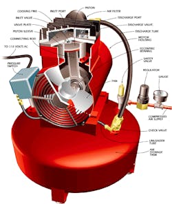
There are different types of compressors that move air into a chamber. Most compressors are positive-displacement compressors in which, by forcing air into the chamber, volume is decreased to compress the air. Reciprocating or piston-type air compressors pump air by using pistons and one-way valves to guide air into the cylinder chamber. Most commercially available compressors are either one- or two-stage compressors. Single-stage compressors are used for pressure ranges from 70 to 100 psi. For larger pressure ranges of 100 to 250 psi, two-stage compressors are used. Single-acting compressors use only one side of a piston and double-acting compressors use both sides of the piston. Compressors have a pressure limit that, once reached, will shut off the compressor. The air will remain stored until used for a kinetic energy application.
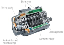
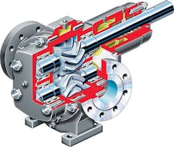
Rotary-screw compressors use helical screws to guide air in the chamber. The screw functions similar as the piston by displacing and compressing air. The most common rotary-screw compressors are single-stage helical or spiral-lobe oil-flooded screw air compressors. These compressors do not have valves and are oil cooled. The oil seals the internal clearances and, since the cooling is performed inside the compressor, the operating temperatures do not rise to extreme temperature levels.
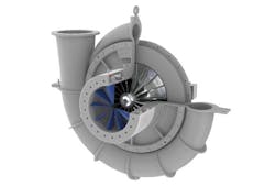
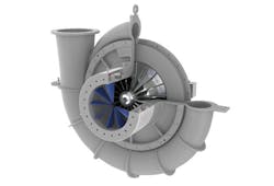
Negative-displacement air compressors or dynamic compressors are typically centrifugal compressors. Using a spinning impeller, a centrifugal force is generated to accelerate and decelerate captured air, which causes it to be pressurized. To control the capacity of a centrifugal compressor, the inlet guide vanes are adjustable. Closing the guide vanes reduces the volumetric flow and capacity.
Types of Pumps
Two basic types classify pumps: positive displacement pumps and centrifugal pumps. Positive displacement pumps move fluid by moving a fixed amount of it and forcing the fixed amount into a discharge pipe. They can produce the same flow at a given speed regardless of the discharge pressure making them constant flow machines. To prevent line bursts, positive displacement pumps typically have a relief or safety valve on the discharge side. If a positive displacement pump operates against a closed discharge valve, pressure inside the discharge increases, causing a line to burst, which damages the pump. Positive displacement pumps can be classified as reciprocating pumps (piston, plunger, and diaphragm), power pumps, steam pumps, and rotary pumps (gear, lobe, screw, vane, regenerative or peripheral, and progressive cavity).
Reciprocating pumps consist of a cylinder with a plunger in which the retract stroke causes suction valves to open drawing fluid into the cylinder. The forward stroke pushes the liquid into the discharge valve. When only one cylinder is used, the fluid flow varies between maximum flow in the middle position to zero flow at the end positions. Significant energy losses are overcome by using two or more cylinders working out of phase with each other. In contrast, diaphragm pumps pressurize the hydraulic oil via the plunger, which flexes the diaphragm in the pumping cylinder. Typically, diaphragm pumps are for hazardous and toxic fluids.
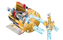
In a rotary gear pump, the opening between gear teeth and the chasing of the pump on the suction side traps the liquid. The fluid is squeezed out on the pressure side when the teeth of the two gears are rotated against one another. Lobe pumps operate similarly to gear pumps except two lobes, being driven by external timing gears, control it in which the lobes never make contact. A progressive cavity pump uses a metal rotor, which rotates within an elastic stator. Progressive chambers from suction end to discharge end form between rotor and stator as the rotor turns, thus moving the fluid.
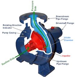
A centrifugal pump converts input power to kinetic energy by accelerating liquid in an impeller. Centrifugal pumps are constant head machines. A volute pump is the most common centrifugal pump. Here, the fluid enters the pump through the eye of the impeller rotating at high speed. As the fluid accelerates radially outward from the pump chasing, a vacuum is created at the impeller’s eye. This vacuum creates more suction and draws in more fluid into the pump. The maximum head is determined by the outside diameter of the pump impeller and the rotating shaft speed.
Head is used to measure the kinetic energy of a centrifugal pump. Head is the measurement of the height of the liquid column the pump can create from the energy the pump transfers to the liquid. Instead of using pressure to measure energy, head is used because pressure can change as specific gravity changes. The head will not change in value. Below is list of different types of pump head. If the shaft of a centrifugal pump is turning at the same revolutions per minute, a pump will pump to the same height regardless of what type fluid. The only difference is the amount of power required to pump different types of fluids. Typically the higher the specific gravity, the more power is required.
- Total Static Head—Total head when the pump is off
- Total Dynamic Head (Total System Head) —Total head when the pump is on
- Static Suction Head—Head on the suction side, with the pump off, if the head is higher than the pump impeller
- Static Suction Lift—Head on the suction side, with the pump off, if the head is lower than the pump impeller
- Static Discharge Head—Head on discharge side of pump with the pump off
- Dynamic Suction Head/Lift—Head on suction side with the pump on
- Dynamic Discharge Head—Head on discharge side with the pump on
- Shut-off Head—Head height of the fluid being pumped when the discharge of the centrifugal pump when is pointed straight up into the air
Head pump is expressed in the following equation:
h = (p2 - p1) / (ρÎg) + v22 / (2g) (1)
where
h = total head developed (m)
p2 = pressure at outlet (N/m2)
p1 = pressure at inlet (N/m2)
ρ = density (kg/m3)
g = acceleration of gravity (9.81) m/s2
v2 = velocity at the outlet (m/s)
