What’s the Difference Between Spur, Helical, Bevel, and Worm Gears?

Download this article in .PDF format
Gears might be “old” technology, but they are still considered the most rugged type of mechanical drives. They transmit power with efficiencies of up to 98% and have long operational lives. That’s why gears and not belts or chains are used in automotive transmissions and most heavy-duty machine drives. Gears are also versatile and can serve to increase output torque by providing gear reduction and also be used to adjust the direction of shaft rotation, such as on the driveshaft to the rear wheels of cars and trucks.
Here's a look at some basic types of gears.
Spur Gears

Spur gears are mounted in series on parallel shafts to achieve large gear reductions.
The most common gears are spur gears and are used in series for large gear reductions. The teeth on spur gears are straight and are mounted in parallel on different shafts. Spur gears are used in washing machines, screwdrivers, windup alarm clocks, and other devices. These are particularly loud, due to the gear tooth engaging and colliding. Each impact makes loud noises and causes vibration, which is why spur gears are not used in machinery like cars. A normal gear ratio range is 1:1 to 6:1.
Helical Gears
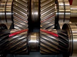
Helical gears have a smoother operation due to the angle twist creating instant contact with the gear teeth. The teeth on a helical gear cut at an angle to the face of the gear. When two of the teeth start to engage, the contact is gradual--starting at one end of the tooth and maintaining contact as the gear rotates into full engagement. The typical range of the helix angle is about 15 to 30 deg. The thrust load varies directly with the magnitude of tangent of helix angle. Helical is the most commonly used gear in transmissions. They also generate large amounts of thrust and use bearings to help support the thrust load. Helical gears can be used to adjust the rotation angle by 90 deg. when mounted on perpendicular shafts. Its normal gear ratio range is 3:2 to 10:1.
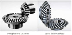
Bevel Gears
Bevel gears are used to change the direction of a shaft’s rotation. Bevel gears have teeth that are available in straight, spiral, or hypoid shape. Straight teeth have similar characteristics to spur gears and also have a large impact when engaged. Like spur gears, the normal gear ratio range for straight bevel gears is 3:2 to 5:1.

The cross-section of the motor in the image (left) demonstrates how spiral bevel gears are used.
Spiral teeth operate the same as helical gears. They produce less vibration and noise when compared to straight teeth. The right hand of the spiral bevel is the outer half of the tooth, inclined to travel in the clockwise direction from the axial plane. The left hand of the spiral bevel travels in the counterclockwise direction. The normal gear ratio range is 3:2 to 4:1.
Hypoid Gears
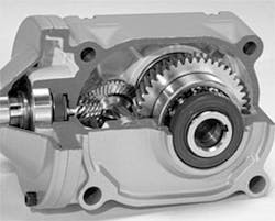
This engine is using a conjunction of hypoid gears and spiral bevel gears to operate the motor.
Hypoid gears are a type of spiral gear in which the shape is a revolved hyperboloid instead of conical shape. The hypoid gear places the pinion off-axis to the ring gear or crown wheel. This allows the pinion to be larger in diameter and provide more contact area.
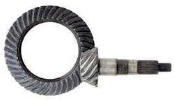
The pinion and gear are often always opposite hand and the spiral angle of the pinion is usually larger then the angle of the gear. Hypoid gears are used in power transmissions due to their large gear ratios. The normal gear ratio range is 10:1 to 200:1.
In the hypoid gear image (right), the larger gear is called the crown while the small gear is called the pinion.
Worm Gears

The model cross-section shows a typical placement and use of a worm gear. Worm gears have an inherent safety mechanism built-in to its design since they cannot function in the reverse direction.
Worm gears are used in large gear reductions. Gear ratio ranges of 5:1 to 300:1 are typical. The setup is designed so that the worm can turn the gear, but the gear cannot turn the worm. The angle of the worm is shallow and as a result the gear is held in place due to the friction between the two. The gear is found in applications such as conveyor systems in which the locking feature can act as a brake or an emergency stop.
