Cam design equations replace graphics
Cams convert rotary motion to oscillatory or linear motion through a follower riding on a cam surface. As a cam rotates, its profile causes the follower to move along its axis or its pivot to bring a machine part into position at the proper time. Cams make it possible to produce complicated motions that cannot be produced by other mechanical means such as linkages.
For example, the internal combustion engine uses cams to open and close valves. Other applications include bottling, canning, and textile machines, printing presses, machine tools, robots, and electromechanical switches.
Design process
In designing a cam, engineers often use the uniform-velocity-displacement curve to achieve the desired motion of a part. However, this curve is impractical for many applications because of step changes in velocity, which occur at the beginning and end of the rise or fall period. These changes produce infinite inertia forces in the follower due to infinite accelerations at these points.
A modified uniform-velocity-motion approach, although seldom used except in low-speed and heavy-duty applications, removes the step changes by smoothing the displacement curve at the end points, using any curve, such as a circular arc or a parabolic curve. This causes the follower to accelerate (or decelerate) more gradually at the beginning and end points, thus achieving a smoother operation.
Textbooks generally describe the modified uniform-velocity method, using circular arcs, only in terms of a graphical, rather than analytical, approach. But, graphical methods for determining the velocity and acceleration from a displacement curve are time-consuming, and they lack accuracy.
By contrast, analytical approaches are accurate and fast, once the general equations for the motion are established. The procedure for developing these circulararc equations is summarized in the following sections (without derivations). These equations can be used manually. However, to further speed the design process, they are available in a software program for use on an IBM-compatible PC.
Defining the geometry
The first step in designing a cam by the modified uniform-velocity method, using an analytical approach, is to define the geometry. Figure 1 shows a typical motion curve (heavy line) that is divided into three regions:
Region 1: Arc at beginning of stroke. Region 2: Straight line. Region 3: Arc at end of stroke. In this figure, let: L= Total lift, in. θT = Period, deg of cam movement. xT = Linear distance corresponding to period θT, in. R = Radius of the circular arcs at the beginning (Region 1) and end (Region 3) of the period, in. Φ = Angle subtended by the arcs in Regions 1 and 3, deg.
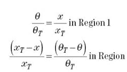
With this geometry, the cam angle θ and the linear distance x for a point on the motion curve are related by:
Motion equations
With the geometric parameters of the curve now defined, the resulting equations for follower displacement, velocity, and acceleration are given as follows: For Region 1:
To illustrate the use of these equations, consider a hypothetical application in which the bed of a printing press moves through one cycle of reciprocating motion while the printing cylinder rotates through one revolution. During the forward stroke, the bed moves a distance of 2 in. while the cylinder rotates 180 deg. It then remains stationary (dwells) for the next 45-deg rotation. Then, the bed returns to the starting position during the next 90-deg and dwells during the last 45 deg of the cycle.
Considering that the bed completes one cycle while the cam rotates 360 deg, we must first develop displacement, velocity, and acceleration versus cam-angle curves for the cam follower (or bed) motion. To obtain modified uniform motion, we arbitrarily choose circular arcs of radii 1 in. and 0.5 in. respectively for the rise and fall portions of the curve.
Thus, for the rise portion of the curve: LR = 2 in. θTR = 180 deg xTR = 4 in. RR = 1 in. and, for the fall portion: LF = 2 in. θTF = 90 deg xTF = 2 in. RF = 0.5 in.
Using the above data, we will design a 2.55-in. base diameter cam for a rollerfollower whose roller is 0.5-in. diameter (dimensions again chosen arbitrarily).
Solution for the rise portion of the curve. First, we determine the angle Φ, using equation (5) and the values for A, B, and C:
By substituting the above values into the appropriate displacement, velocity, and acceleration equations for the required angles, we get the results in Table 1 and the curves in Figure 2a.
Solution for the fall portion of the curve. The same basic procedure is used to calculate the required angles and distances. Then, by substituting these values into the appropriate motion equations, we get the results in Figure 2b. The cam layout, based on this calculated data, is shown in Figure 3.
Lyndon O. Barton is a senior engineer at E.I. Du Pont de Nemours & Co. and an adjunct instructor at The Delaware Technical& Community College, Newark, Del.
About the Author
Voice Your Opinion!
To join the conversation, and become an exclusive member of Machine Design, create an account today!

Leaders relevant to this article: