What's the Difference Between Cartridge Heaters and Tubular Heaters?
This file type includes high resolution graphics and schematics when applicable.
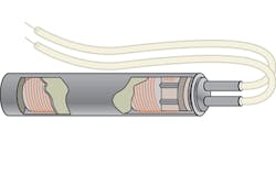
A cartridge heater is an industrial heating element. It consists of an outer metal enclosure called a sheath containing resistive wiring separated from the sheath by electrical insulation. Most cartridge heaters are straight cylindrical tubes and have diameters designed to slide into holes drilled with common English or metric drill sizes. (Some manufacturers advise reaming holes after drilling for high-watt density heaters.)
Typical cartridge heater diameters range from 1 in. (English) or 20 mm (metric) at most down to 1/8 in. (English) or 4 mm (metric). Smaller cartridge diameters are possible but the wattages are limited by the small surface areas associated with these diameters. Lengths vary by diameter but can range from 8 ft down to less than an inch.
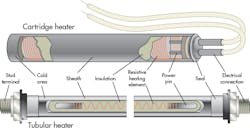
A cartridge heater consists of the metal sheath, power pins, resistive wire, insulation, sealing at one end of the sheath, an electrical connection between the resistive wire and power pins, a termination of the resistive wire into wire leads, and the leads themselves.
Tubular heaters
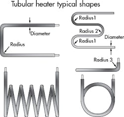
Cartridge heaters are sometimes confused with tubular heaters. Cartridge heaters are generally cylindrical or rectangular with no bends or other geometrical shaping or curves. They are basically designed to insert in drilled blind holes. Tubular heaters, on the other hand, may be formed into complex geometries with a variety of lengths, diameters, terminations, and sheath materials. Whereas cartridge heaters typically slide into drilled holes, tubular heaters may be welded to metal surfaces or cast into metals. They often are inserted into ovens, chambers, and vessels.
Tubular heaters are used for immersion and air heating. They often get clamped to objects such as vessels and tanks, fitted into milled groove platens, immersed directly into a liquid, or even are mounted in ducts for heating air and gas. They may also be available in single and double-ended versions.
The internal make-up of tubular heaters resembles that of cartridge heaters. They generally contain a helical Nichrome resistive wire that serves as a heating element. It is welded on each end to terminal pins. The heating element is centered in the sheath which is filled with MgO. The MgO is compacted to stabilize the coil and promote heat transfer to the sheath.
Because cartridge heaters have a simpler geometry, they can sometimes provide a higher surface-watt density than tubular heaters. The reason is that their heating elements can lay closer to the sheath surface than in tubular heaters where the resistive wire may have to accommodate bends or changes in geometry. Also as a consequence of the simple geometry, cartridge heaters may be fabricated in diameters down to about 1/8 in. where the minimum diameter for tubular heaters is usually ¼ in.
This file type includes high resolution graphics and schematics when applicable.
Materials used, cartridge heaters, and tubular heaters
This file type includes high resolution graphics and schematics when applicable.
Sheaths: Both cartridge heaters and tubular heaters may use Incoloy nickel-based alloys and stainless steels in their sheath materials. In addition, tubular heater sheaths may often be copper, when used in water heating, or low-carbon steel, when used for heating tar, asphalt, or similar materials.
Electrical leads: Cartridge heaters typically have both electrical leads brought out to one end of the sheath. The electrical leads can be insulated with various materials depending on the amount of heat the leads must withstand. Tubular heaters typically have one electrical termination at each end of the tube. The terminations may be wire leads but more typically are threaded studs or lug terminals separated from the body of the heater with a ceramic or mica insulator. (It is possible to find “single ended” tubular heaters with both electrical leads emerging at one end, like cartridge heaters. But such configurations are usually special-order items.)
Mounting: Cartridge heaters typically slide into open holes, rather than blind holes, drilled to accept them. Installations generally stay away from blind holes because the extraction of the heater from a blind hole can be problematic in the presence corrosion or debris.
Tubular heaters may be brazed, soldered, or welded onto surfaces they heat. But the most widely used mounting approach is with a mounting collar or bracket, particularly for containers that are not pressurized and which aren’t sealed to hold liquid. The usual way of attaching the heater to the bracket is with staking or crimping. Bulkhead fittings are used to mount heaters through tank walls. The connection method to the heater depends on such factors as the amount of pressure or vacuum present and the qualities of gas or liquid being heated.
Moisture seals: Neither cartridge heaters nor tubular heaters are 100% sealed against moisture. That is a point to remember in that both use MgO insulating material, which is hygroscopic. In many cases, both kinds of heaters will dry themselves out when turned on. In superhumid environments, more exotic sealing materials such as silicones, RTV, or epoxies can be employed to minimize the risk of moisture-induced short circuits.
Sheath forming: The sheaths used for cartridge heaters typically are cold swaged where the cylindrical form is put through a confining die to reduce its diameter using a method analogous to that of drawing wire. The process may also be referred to as "tube swaging." Tubular heater sheaths typically go through a roll-reducing mill and then get annealed to relieve the work hardening that rises during the rolling and size reduction. They can then be bent either in the factory or in the field while undertaking precautionary measures to prevent the sheath from breaking or developing stress cracking marks. Heating elements with tight bends may need to go through special dies used to ensure the MgO insulation material maintains its dielectric strength.
This file type includes high resolution graphics and schematics when applicable.
About the Author
Leland Teschler
Lee Teschler served as Editor-in-Chief of Machine Design until 2014. He holds a B.S. Engineering from the University of Michigan; a B.S. Electrical Engineering from the University of Michigan; and an MBA from Cleveland State University. Prior to joining Penton, Lee worked as a Communications design engineer for the U.S. Government.


