6 Factors to Consider Before Moving to Automated Inspection
This file type includes high-resolution graphics and schematics when applicable.
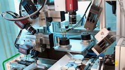
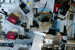
If you’re producing small precision components, quality drives the entire manufacturing process. One of the ways to help ensure the quality of such products is through the use of automated inspection systems known as automatic visual-control systems (AVCs).
These systems use computer visual technology to automatically check parts for many different defects (e.g., contamination, scratches, dents, or deformations caused by faults in production) and specifications (mainly dimensional abnormalities). They also gather data that helps improve manufacturing efficiency, geometric dimensioning, and tolerancing. Most importantly, considering that labor costs vary regionally, automated inspection costs less than manual inspection and the payback is generally two years or less.
Before migrating to automated inspection, though, a company should pay attention to the following six key factors.
1. Each part gets its own solution.
Designing an AVC to test different part types has proven to be a difficult task, as part geometry can become occluded or shadows can hide relevant areas. These limitations are typically the result of the product’s design, since automatic inspection is not part of the product design process. The defect specification, lighting, resolution, and/or camera speed—defined by lighting and process cycle time—can help get an accurate analysis.
Whereas a human operator has a chance to get a second look at a part if something is suspicious, a machine cannot. Every eventual defect condition has to be considered during the AVC design process. Even similar parts have their own challenges related to a specific material or product design, so finding customized approaches are necessary.
If a company is looking into AVCs for quality inspection, it makes the most business sense to start with the company’s highest volume parts or parts that are very similar, such as O-rings. An O-ring inspection system can inspect a variety of different parts. Configuring a system to test different types of O-rings is less challenging because O-rings are very similar to one another and have simple geometries; thus, inspecting different part types is possible with a single system.
2. Dimensional measurement and surface inspection.
Two different types of AVCs can be found on the factory floor. The first type is mostly for dimensional measurement, while the second is for surface inspection. Of the two, dimensional-measurement systems are the easiest to develop. Also, statistical methods (e.g. measurement system analysis) that compute the capability of a solution are easy to design for a machine, since everything around the AVC can be estimated in advance. By clearly defining part specifications, a system can identify critical parameters, those dimensions with the tightest tolerances. Once these critical parameters are found, the capability of a system are able to rogrammed properly, l methods., the capability of a syustem wn lighting, higher speed or resoluution daking the arecan be validated with statistical methods.
Surface inspection, on the other hand, can be very challenging. Having documented instructions tell human quality inspectors what to look for when manually inspecting a part will aid AVC development. However, these instructions do not provide enough guidance to software engineers developing the program for an AVC. While the instruction might be perfectly understandable to a human inspector, software developers need to be given more guidance.
For example, a quality instruction might state that a particular type of defect is “not allowed.” Interpreted literally, this would require the inspection system to have infinite resolution. Instead of simply saying “not allowed,” developers must be provided with quantifiable defects so that they can appropriately design the system. If very small defects are not allowable, the system needs to be able to “see” them and, therefore, requires higher resolution.
Companies often face two challenges: A defect needs to occur and have been noted before it can be corrected; and communicating defect-specific characteristics with a computer can be difficult. As a result, companies typically implement a “base” inspection for all areas to at least have the chance to find unknown defects. Machines are traditionally built on the basis of those defects, since they are already available. Some defect prediction may be feasible, but bears the risk for increased “pseudo” rejects.
Coming to a consensus on the size of defects can be difficult, because a number of factors must be taken into account. Quality engineers have to work with the design engineers, and even machine suppliers, to come up with the appropriate numbers.
3. Cataloging defects.
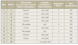
Because defining and categorizing defects is such a critical part of the development process, quality engineers should produce a defect catalog before beginning AVC development. The defect catalog is not only a list of all defects that the system must be able to detect, but also a collection of parts that have defects at or near the borderline of acceptability. The reason these parts are so important is that the system will be validated exclusively by inspecting them.
As shown in the spreadsheet, the defect catalog includes the type of defect, where that defect is to be found, defect severity, probability, and the critical size of the defects, if relevant. All of this information helps the software developer prioritize the detection of common defects.
For each defect, it is desirable to have at least two samples, with one being a borderline defect. Depending on the complexity of the part, defect catalogs will typically have 60 to 100 parts. It’s usually preferable to have “more than enough” parts, as it is easier to identify parts that do not add knowledge to the catalog, rather than discover that important information is missing.
The biggest challenge in developing the defect catalog concerns communication between the quality department and the AVC developer. The AVC developer needs to have an understanding of the production process, and the quality department must understand the limitations of the inspection system.
Quality engineers, for example, understand the term “flash” (which is produced by rubber being pressed into the tool separation line). However, the specific characteristics, such as shape, softness, and thickness, must be described in some detail to the AVC developer to ensure that the system will find defective parts and not reject good ones. Depending on the cause, the defect may be a wide thin area (meaning the compression was too high) or a small thin fiber (meaning the tool had a scratch). Detecting these may require different approaches.
4. Program for finding defects.
To reliably find a particular defect, the program must perform five steps:
1. Part localization: The program must locate the part in the image, compensating for slight variations of the handling system.
2. Image segmentation: The program splits the image into functional areas of interest. Each area is defined by a limited set of defects and as a single function in relation to the part, such as seal lip, outside diameter, top face, and so on.
3. Image normalization: Remove everything from the image that it would normally find in a good part. This includes design/feature lines and common product variations. This is a core function, as it compares each new image with the history of good parts and highlights deviations from this history.
4. Signal/noise optimization: At this point, the program filters the image to extract possible defects from known noise. This step takes specific defect features, such as dark contamination, bright marks, and vertical flow lines into account.
5. Defect detection and classification: Finally, the program identifies suspicious regions and assigns a classification value, which is used to a make a pass or reject decision. In addition, the program notes whether or not the part has any acceptable defects. This data can be used to head off production problems before they occur.
5. Ensure a good image.
A good inspection relies on a quality image. Here, companies can do several things to ensure that the AVCs produce the best possible image. Image quality typically depends on the illumination and camera setup, but one also has to consider the type of defect. Other factors include minimizing the number of false rejects; staying within the required cycle time; and making the best use of available machine space.
The best setup is typically through experimentation. In addition to analyzing different images from defective parts in the defect catalog, companies should also experiment with images of production parts to represent process variation. Based on these findings, a preliminary investigation from the AVC expert is done, which typically reveals the required setup.
As an example, a company can take images of its parts made before and after tool cleaning, or made with different tool sets, to give it an idea of how process variations will affect image quality. By analyzing the images and applying its knowledge of the image-processing software’s limitations, the company would be able to come up with a workable solution. Software limitations sometimes mean that the company has to develop a more complex lighting and camera setup. At other times, hardware limitations increase program complexity or development times, or in some cases, means that you have to live with more false rejects than you’d like.
6. Big investment = big payoff.
For any company, developing and installing AVCs has been a big investment, but it's an investment that generally pays off. The biggest benefit is reduced cost, since automated inspection costs less than manual inspection. Another benefit is AVC, if programmed correctly, greatly reduces the risk of performing a bad inspection and delivering defective parts. It can also detect anomalies that are not quite yet defects. The data can alert engineers to problems, so they are able to make corrections before defective parts are produced.
AVC systems have reduced the number of customer complaints, and for some part types, the complaint rate has dropped to zero. This trend may continue to grow, as “smart systems” that train themselves how to find parts that differ from the typical products are already being developed. Smart systems may allow AVCs to gain even more traction, as they have the ability to reduce the risk of programming errors, as well as the time and cost to implement a new solution.
Dr. Helmut Hamfeld studied computer science at the University of Kaiserslautern and earned his PhD in 3D-scanning technologies. After working on 3D human-body visual scanning, automated car-body inspection, and general image processing at different German companies, he became responsible for automated visual-control systems for Freudenberg Sealing Technologies GmbH & Co. KG.
Looking for parts? Go to SourceESB.
This file type includes high-resolution graphics and schematics when applicable.


