LED/Photodetector Array Provides Non-Contact 2D Mapping of Blood Oxygen
You’re undoubtedly familiar with the clip-on blood oxygen sensor and meter that uses a pair of LEDs and a photosensor. This non-intrusive transmissive-light device—which took decades to develop, prototype, verify, and achieve widespread use (see References below; they, in turn, contain additional references)—effortlessly provides real-time monitoring of blood oxygen saturation (SpO2). You can buy one at pharmacies and department stores for about $20. It’s a vast improvement in so many obvious ways compared the previous method of determining SpO2, which required drawing blood samples from the patient and sending them to a lab, then waiting for test results.
This pulse-oximetry approach implements a ratiometric optical measurement on pulsatile (pulsing) arterial blood via photoplethysmography (PPG) at two different wavelengths. It does have limitations, as it works only with skin tissues that can be transilluminated, such as the earlobes and the fingers. However, both medical researchers and practicing doctors often want to know the oxygenation situation as a two-dimensional map across a section of the body such as the forehead, forearm, or areas of surgery including tissue, wounds, skin grafts, and transplanted organs.
To address this issue, a team at University of California at Berkeley, working with Display Technology Limited (UK), developed a 2D oxygen-saturation reflectance oximeter array (ROA) that senses reflected light from tissue and makes the saturation measurements.
This flexible electronic system is constructed by printing and integrating arrays of organic optoelectronics, supported by standard ICs already used for blood and tissue oximetry. The combination of red and near-infrared (NIR) light (sometimes, red and green) is used for oximetry because of differing molar extinction coefficients (absorptivities) of oxyhemoglobin (HbO2) and oxyhemoglobin (Hb) yields ratios that correspond to oxygen saturation.
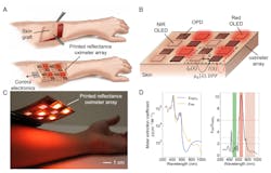
The ROA is composed of four red (612 nm) and four NIR (725 nm) printed organic light-emitting diodes (OLEDs) and eight organic photodiodes (OPDs). The OPD and OLED arrays are fabricated on separate substrates and then assembled together to form the ROA sensor array (Fig. 1).
1. Overview and operation of the printed reflectance oximeter array (ROA): Schematic of an application scenario of the ROA—2D oxygenation mapping of a skin graft on the forearm (A). After surgery, the ROA is placed on the skin graft to map oxygenation of the reconstructed skin. ROA sensor configuration; red and NIR OLED arrays composed of 2 × 2 pixels each are placed side by side, arranged in a checkerboard pattern (B). The OPD array composed of 8 pixels is placed on top of the OLED arrays. I0(λ) is the incident light intensity; OPDs are used to collect the diffused reflected light, I(λ). The OLEDs and OPDs are spaced at d cm (emitter-detector spacing). µa(λ) is the absorption coefficient of the sensed tissue, which depends on the specific absorption coefficients and concentration of HbO2 and Hb, and DPF is the differential pathlength factor. Photo of the ROA on top of a person’s forearm (C). The molar extinction coefficients of HbO2 and Hb and the ratio of the molar extinction coefficients of Hb and HbO2 (D). Three regions are shown: (i) green (εHb/εHbO2 <2), (ii) red (εHb/εHbO2 >6), and (iii) NIR (εHb/εHbO2 <3). (Either of the combinations of “red and green” or “red and NIR” can be used for oximetry.)
The active area for both OLEDs and OPDs is 0.7 × 0.7 cm with 0.5-cm spacing between the OLEDs and OPDs, so the complete ROA is 4.3 cm in both length and width. Each “pixel” of the ROA is composed of one red and one NIR OLED and two OPDs. Signals from the red and NIR channels are read out sequentially using the two OPDs, and the average of the OPDs is used for signal processing. With this format, the 4 × 4 device (OLEDs and OPDs) array provides 3 × 3 readout pixels. The pixels are selected using analog switches; an analog front end (AFE) sequentially drives the OLEDs and reads out the OPD signal.
The control electronics were designed to support reflectance oximetry in the single-pixel and the array mode. A Texas Instruments AFE4490 AFE was used to sequentially drive the OLEDs and read out the OPD signal, and the OLED and OPD arrays were interfaced with the control electronics using flexible-flat-cable (FFC) connectors. The pixels in the array were selected using analog switches (Analog Devices ADG1608) and the AFE was controlled with an Arduino Due microcontroller. The software control of the AFE provided flexibility in choosing OLED driving parameters and allowed for adjustments to the variable OPD-gain circuitry.
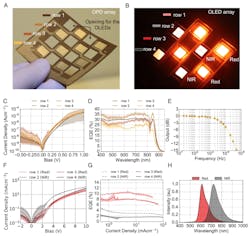
The emitter-to-detector spacing parameter “d” is an important design parameter for successful reflectance oximetry, as both ac and dc signal magnitudes drop exponentially with increasing d. To find the optimal value for d, the team used a reflection-mode sensor board and measured the effect of d on PPG ac and dc signals at the eight locations on the body. The final sensor has three rings of four OPDs spaced 0.5 cm, 0.8 cm, and 1.1 cm away from the red and NIR LEDs at the center (Fig. 2).
2. Photographs and performance parameters of the OPD and OLED arrays: (A) OPD array composed of 8 pixels with 2 pixels in each row. The rows are marked using different shades of brown markers, which represent the legends of performance data presented in C and D. (B) Red and NIR OLED arrays: 2 × 2 red OLED array in rows 1 and 3 and 2 × 2 NIR OLED array in rows 2 and 4. The rows are marked using red and gray markers, which represent the legends of performance data presented in F and G. (C) Current density vs. voltage bias (JV) plot for the OPD array; each trace represents mean of the data in that row, while the shaded region shows the range of the data. (D) External quantum efficiency (EQE) of the OPD pixels in the array as denoted by row position in accordance with the colors in A. (E) The frequency response of an OPD pixel. The 3-dB cutoff is at over 5 kHz. (F) JV characteristics of the red and NIR OLED arrays as denoted by row position in accordance with the colors in B. (G) EQE as a function of current density of OLED arrays. (H) Emission spectra of the red and NIR OLED arrays.
The OLEDs were driven at 10 mA/cm2 with the red OLEDs providing 0.9 mW of optical flux, while the NIR OLEDs provided 0.2 mW of flux. A two-stage OPD gain circuit was used to amplify the photocurrent—a 100-kΩ feedback resistor was employed in the first stage, while the second stage was operated at unity gain. The acquired data was transferred via a USB interface and processed using custom in-house software.
While the hardware is important, the software and algorithms that analyze the and apply various corrections and compensation factors are also critical to both this reflected oximetry (as they are to the fingertip/earlobe pulse oximeter, of course). Among the many results provided, tests on the forehead had a 1.1% mean error compared with a commercial transmission-mode pulse oximetry.
Their 2D reflected oximeter and its algorithms offer another unique advantage over pulsed oximetry: In the case of a medical shock, low blood perfusion, or organ injury, the pulsing arterial blood signal of PPG becomes too weak to be used for pulse oximetry. For patient scenarios and body locations with a low pulsatile PPG signal, the team was able to demonstrate a method of determining oxygenation despite the absence of the viable pulse, which is essential for the transmissive approach.
Details of the project are in their paper “A flexible organic reflectance oximeter array” published in the Proceedings of the National Academy of Sciences, and includes extensive results of many various tests and assessments the team performed.
References
EE World Online, “Blood oxygen meters, Part 1: Background and principles”
EE World Online, “Blood oxygen meters, Part 2: IC implementations”


