Anatomy of a Machine Tool Tending Cell: Robotics, Vision Systems, Mobile Automation
A typical machine tool tending cell combines multiple technologies to operate efficiently. This includes robotics equipped with specialized grippers and end-of-arm tooling, vision systems for inspection, machine interface software that communicates with CNC machines, safety systems and Industry 4.0 connectivity to enable data sharing and cloud integration.
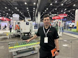
In the accompanying video, Ed Volcic, North American chief regional technology officer, Kuka Robotics, provides a play-by-play of a machine tool tending cell.
Ed Volcic’s transcript below has been lightly edited for clarity.
Automation Cell Setup and Workflow
[0:02] Starting here on the right side of the cell, you’ll see that the overall setup of this particular automation solution is something you typically see in a machine shop.
You have raw materials coming in on the very right-hand side, a robot processing those raw materials and ultimately being delivered to a machining center where the machines are processed.
READ MORE: Reverse Mic: NVIDIA, Teradyne Thought Leaders Compare Notes
You can see the robot is using bin picking technology here to identify a bin full of parts, identify parts that it can pick out, simulate and put them onto a tray which will be then transported over to a machining center.
Bin-Picking Technology with 3D Vision
[0:41] The interesting technologies here in the vision system include a photo nail bin picking solution. Photoneo is a 3D vision solution [now part of Zebra Technologies], which identifies randomly placed parts inside of a bin and gives information to the robot system to then go and pick those parts inside the bin.
Once the robot successfully picks the part out of the bin, it places it onto a tray. It's actually placing it onto a little stand here where it’s reorienting it so that it can place it successfully onto a tray.
Once the robot has put a number of parts onto the tray, you’ll see here it’s being serviced by a Kuka mobile platform, in this case the KMP 1500P, which is capable of lifting up to 1,500 kilograms in parts.
Tray Loading and Robot Reorientation
[01:32] What the KMP is doing here is waiting for the tray to be filled up. Once it’s filled, it is going to remove that full tray from that cell, spin around, place an empty tray back into that cell so that the robot can keep moving forward with its bin picking operation.
READ MORE: The Robots Are Ready; Are We?
Then the KMP is going to deliver the parts over to a machining center...As you can see right here, the robot is removing a full tray of parts. It will turn around, place an empty tray into the fixture, and then you’ll see it move over to the machine tool.
[02:22] The KMP uses SLAM navigation, which is using LIDAR or lasers embedded in the robot to scan the environment and look for the station that it's docking into. In this case, it is docking into the stand, where it is going to place the empty rack.
Once placed, the KMP is going to move forward and move over to the station where it is going to deliver the parts.
Tray Handling and Tray Exchange
[02:50] While this is going on, you can see a second KMP just off to the right of the first KMP, which has a conveyor system mounted to it. The conveyor system in this case is used to transport bins of parts from a full station to the station where they’re going to be unloaded by the robot.
[03:10] Now let’s follow this KMP 1500P here, which is going to deliver parts to a machining center. In this case, the machining center is being serviced by a Kuka Agilus robot.
Programming Interface: Sinumerik and mxAutomation
What’s interesting about this particular cell as the machining center here is using Sinumerik by Siemens and Kuka’s mxAutomation to interface with the Kuka robot controller.
READ MORE: A Business Case for Advanced Machine Vision in Factory Automation
mxAutomation provides an easy-to-use interface for Sinumerik programmers to be able to easily program the Kooka Robot and interface with it. These programmers don’t need to know the Kuka robot programming language. They can simply use the tool set that they’re comfortable with, using Sinumerik to do all the programming and coordination of the robot as it picks parts from the trays, places it into the machining center, and then pulls parts out of the machining center and dumps them into the bin.
[4:17] Here the robot is identifying parts on the tray to pick, placing them into the machine tool where they’re going to be machined. Once the machining is done, the parts are pulled out of the machine and placed into the bin.
Payload Capability and Fleet Management
[4:36] The KMP 1500P here, the platform that’s moving the parts between the stations, has in it an integrated lift which is capable of lifting a 1,500-kilogram payload, lifting it out of the station and moving it to a different station.
All of the KMP’s movements are being managed through Kuka's fleet management software, Kuka.AMR fleet, which coordinates and sends all of the missions to each of the KMP 1500Ps to go and pick up trays, or move trays or bins in a coordinated fashion. The fleet management software handles all of the traffic management panels and all of the requests from each of the cells for pickup and drop-offs.
[5:38] And now you can see the KMP 1500P delivering a full tray of parts over to the machining center where they’ll get processed by the robot.
That’s the whole demo.
About the Author

Rehana Begg
Editor-in-Chief, Machine Design
As Machine Design’s content lead, Rehana Begg is tasked with elevating the voice of the design and multi-disciplinary engineer in the face of digital transformation and engineering innovation. Begg has more than 24 years of editorial experience and has spent the past decade in the trenches of industrial manufacturing, focusing on new technologies, manufacturing innovation and business. Her B2B career has taken her from corporate boardrooms to plant floors and underground mining stopes, covering everything from automation & IIoT, robotics, mechanical design and additive manufacturing to plant operations, maintenance, reliability and continuous improvement. Begg holds an MBA, a Master of Journalism degree, and a BA (Hons.) in Political Science. She is committed to lifelong learning and feeds her passion for innovation in publishing, transparent science and clear communication by attending relevant conferences and seminars/workshops.
Follow Rehana Begg via the following social media handles:
LinkedIn: @rehanabegg and @MachineDesign
YouTube: @MachineDesign-EBM