Controlling Brushed DC Motors Using PWM
Download this article in PDF format.
Many applications using miniature brushed DC motors require motors to operate at more than one load point or through specific load cycles. Running a motor at usable load points requires a variable, controllable power source. This can be done by a continuous linear regulation power supply or pulse width modulation (PWM).
Linear regulation is generally inefficient and a requires a larger housing. Moreover, in battery-driven applications, it is impractical to use linear regulation at varying load points. PWM voltage regulation, on the other hand, is efficient and can be used effectively with battery or DC power-driven applications. The better efficiency of the PWM drive increases battery life and reduces heating in electronic components.
One trade-off of using PWM with a motor are the eddy current losses in the rotor windings due to the continuous PWM switching which, in general, are not present in linear power sources. However, properly designed PWM minimizes eddy current effects and improve how the motors are driven.
Core-less brushed DC motors have low inertia and inductance. This lets them be used in applications needing dynamic behavior and fast responses from the motor. Using PWM allows precise current control in the windings. Hence, the output torque, which is linearly proportional to the average winding current, can be correctly controlled in coreless motors.
Unlike pure resistive loads for DC motors, the resistance, inductance and back EMF on the rotor windings are deciding factors in optimizing PWM frequency and duty cycle.
Linear vs. PWM Power Supply
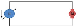
With a linear DC source (as in the figure below), current is a function of just the winding resistance. Inductance does not affect the current as at constant source. An inductor’s impedance is zero.
The catalog values and life prediction for most coreless motors are estimated using a constant, linear DC power supply.
When using a PWM source, the circuit sees Ohmic resistance and inductance due to frequent switching. Moreover, a back EMF equivalent to the motor characteristics (KE) and speed is generated across the terminal. This complicates the PWM circuit when designing it for a specific application, as not only the duty cycle but the frequency of PWM needs to be controlled precisely to get the best motor performance.
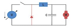
When the motor is at rest or rotating at a low speed, the back EMF can be neglected. The simplified equivalent circuit of the motor is shown below.
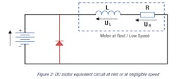
The free wheel or snubber diode (parallel to the motor terminals in the above schematic) should never be omitted when using a varying voltage such as with PWM. The diode lets the charge dissipate without arcing when switching.
When the motor runs at moderately high speed, the back EMF is comparable to the applied voltage, so a component representing the back EMF needs to be added to the equivalent circuit. The modified equivalent circuit is shown in below.
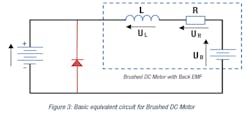
The back EMF, along with the RL circuit in a brushed DC motor, brings non-linearity to the PWM control and the PWM frequency and PWM duty cycle become significant for getting the best output power.
When PWM drives the motor and electromagnetic compatibility is critical, it is recommended to analyze radiation effects because the radiated electromagnetic energy is generally higher with PWM than with DC linear sources.
Voltage-Current Characteristics
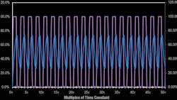
When voltage is applied across an RL circuit, the inductor opposes current through the circuit. As a result, current rises exponentially to a steady-state value that depends on motor’s L/R ratio. The graph below shows the exponential rise in the current through the winding in an RL circuit. When the applied voltage is removed from the circuit, the current slowly falls to zero, decaying exponentially.
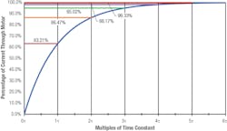
The L/R constant (aka the time constant for an RL circuit) defines the applied voltage’s maximum rate of change in the circuit. The steady state, after any change in applied voltage, is reached after a period equal to several time constants. The graph of the motor’s current (above) shows its exponential rise, which represents an ideal scenario. Five times the time constant (5L/R) is generally considered the time needed to get to steady state. However, at five times the time constant, the circuit is at about 99.33% of its maximum value.
Ignoring the presence of back EMF for simplicity, current rise in a simple RL circuit can be given as:

Where
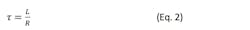
I0 is the maximum current through the RL circuit for a given voltage.; τ is the time constant of the RL circuit defined as the time needed for the current to reach 1/e, or about 63.21% of the maximum current; and t is the time.
Once steady state is reached, if the supply is disconnected, the current through the RL circuit decays exponentially (as shown below).
PWM Design Considerations
When a PWM drive is used with brushed DC motors, the rotor’s internal inductance acts as a current filter which is good for the drive circuit. However, other design parameters, such as PWM frequency and duty cycle, affect the current ripple and, therefore, the life of the brushed commutation.
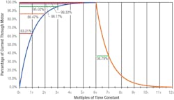
When PWM drives a motor, the current across the motor rises and falls with every period of the PWM. Ignoring the motor’s back EMF, the current rise is a function of motor inductance and total resistance. For every PWM cycle, the PWM frequency should be chosen so there is enough time for the current to reach its steady-state value, which is typically more than 5τ. The graph below shows the conditions when the PWM frequency is enough for the steady state to be reached.
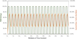
As the PWM frequency increases past threshold value, the PWM on-and-off time becomes shorter than the time required for the RL circuit to operate and the current to reach steady state. Hence, the current oscillates between two non-steady state values, which causes current ripple. The graph below shows the condition when the PWM frequency is higher than the time needed for steady state and the current through the motor oscillates.
From a design perspective, current ripple should be reduced by adjusting the driving frequency so that output torque is nearly linear. It is also advisable to keep the PWM frequency higher than the human range of hearing (above 20 kHz) as a current ripple in that frequency range can create noise during motor operation.
Current Ripple
For specific coreless brushed motors, current ripple should be kept as low as possible. Typically, ripple below 10% is considered a low value. A higher rippleaffects performance in several ways: The motor’s output torque is proportional to current, whereas Ohmic (resistive) heating in the winding is proportional to the square of the current. So, at peak currents, heating in the windings would dominate and decrease motor performance and life. Portescap’s brushed DC motors do not use iron laminations, so eddy current and hysteresis losses in the magnetic circuit are directly proportional to the current ripple and would reduce the motor’s overall performance. For precious metal commutation, increased electro-erosion affects the motor’s life because electro-erosion is proportional to the factor L x Ieff2. where L is the inductance and Ieff is the effective current through the winding. For carbon brush commutation, increased current ripple increases the patina accumulation. (Patina or film is the copper oxide layer formed on the commutator surface of the carbon brush which improves commutation and reduces friction.) Therefore, at lower speeds, brush contact would deteriorate. At moderate-to-high speeds, the patina would not significantly affect motor performance.
The inductive voltage across the terminal can be given as:
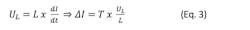
Where L is the inductance; UL is the voltage generated across the inductor; and T is the infinitesimal time it takes the current to change by ∆I.
For PWM motor operation, the voltage across its terminal is opposed by the back EMF generated across the motor terminal. Hence, Eq. 3 can be rewritten for both the current rise and current fall in PWM operations as:

and:

Where the subscript ON denotes the “on” time and OFF denotes the “off” time of the PWM pulse so that the total time TP is given as:

From Eq. 5,

Inserting the value from Eq. 7 into Eq. 4, we get
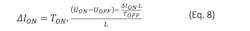
TON and TOFF in the above equation can be given as

and

Where D is the duty cycle of the PWM signal.
Hence, Eq. 8 can be rewritten as:

Eq. 11 can be used to extract the current ripple in the motor due to a PWM signal of duty cycle, D, and frequency, 1/TP.
It is interesting to note from Eq. 11 that current ripple is at a maximum when the duty cycle is 50%. Consequently, it is suggested that designers run the motor away from 50% duty cycle zone.
Also, from the above equation, current ripple depends only on the motor inductance, not the motor’s electrical time constant.
Ideally, for coreless motors, the difference (UON – UOFF), sometimes given as ∆U, should be kept as low as possible, depending on maximum motor input voltage and application speed.
The motor’s inductance across its terminal is a function of the PWM frequency. For example, a catalog lists a Portescap motor’s inductance at 1 kHz; but at 100 kHz, inductance can decrease to as low as 20% of the catalog value.
Compared to iron core motors, coreless motors’ inductance is lower by a factor of two. Also, the Quality factor is poorer as there are no iron laminations in the rotor windings. Hence, a PWM drive with a coreless motor will have relatively higher losses and offer less electronic stability.
Motor Life
In brushed DC motors, the most common failure mode is wear on the brushes due to commutation. During the motor’s lifetime, the brushes (carbon-graphite or precious metal) are spring loaded and mechanically coupled with the collector segments to charge the coils. This makes brush wear a function of mechanical friction generated when the brushes slide over the collector segments and electro-erosion caused by electrical discharges at the time of commutation.
When using PWM drives to run a motor at various speed and load points, the estimated motor life becomes a complex combination of various factors driving its wear properties. These factors can include: Higher current density in the commutation because of reduced efficiency, high mechanical friction, insufficient lubrication or current recirculation. High electro-erosion during current spikes when using PWM sources. Higher working temperature of the motor due to environmental conditions or higher power density of the motor which reduces the lubrication quality.
Depending on the application and source used to power the motor, its life expectancy may depend on one or more of the factors described above.
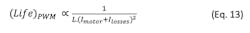
For motor designs where the load point requires the motor to run at moderate torque and speed, with no axial and radial loads acting on the shaft and in a moderate temperature range (typically below 60°C), wear is generally dominated by electro-erosion. Then motor life is inversely proportional to the inductance and square of the current:
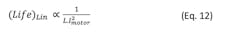
The above equation considers a linear or PWM source with current ripple negligible compared to the average current through the motor. In practical scenarios, the ripple can contribute to reduce the motor life significantly.
Case 1: Current ripple is less than 10%. To reduce current ripple to less than 10% in a Portescap brushed DC motors, the frequency range can be as high as 40 to 120 kHz.
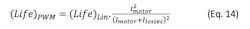
With PWM, Eq. 12 can be rewritten as:
llosses are losses in the diode and losses due to Eddy current and hysteresis on the motor tube. These losses reduce the motor’s overall efficiency. However, a good design would yield about 85 to 90% efficiency of the PWM.
From Eq. 12 and 13, and taking into account llosses as 10% of Imotor .
Then:
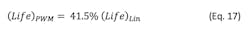
Hence, with 90% of PWM efficiency,

Case 2: Current ripple is significant. Eq. 14 holds true when Ilosses is low compared to Imotor. But when current ripple is high, instantaneous current surges through the motor and heats it; the equation should then be modified to become:

Considering a PWM with 50% duty cycle where ripple is maximum and average motor power is P, the integral part can be re-written as:
Thus, Eq. 16 can be re-written considering 90% of PWM efficiency as:
PWM Increases Motor Life
There are a couple of things that can be done to improve motor life when using PWM:
1. Reduce motor current ripple. Current ripple can be reduced by increasing the PWM frequency. If the PWM frequency is significantly higher than the motor’s time constant (L/R), ripple is further reduced. For Portescap coreless motors, a ripple of less than 10% is recommended for longer motor life.
Another intuitive approach to reducing current ripple is to add external inductance in the motor circuit to act as a current filter. This generally improves efficiency. However, the inductor worsens the overall electro-erosion of the brush-commutator system as electro-erosion is directly proportional to the circuit’s inductance. Hence, unless efficiency and motor heating are the only concerns, this approach is not recommended.
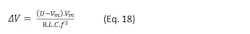
2. DC-DC converter design. In designs such as the one below, system efficiency improves drastically and the motor brush life is longer compared to the solution where an external inductance is added to the circuit.
To optimize the circuit, the voltage ripple, given by eq. 18, should be minimized. A value of less than 10% is good enough for practical motor operations.
Ultrasonic vibrations can be induced in the rotor when driving the motor at lower frequencies. It is therefore suggested to drive the motor at frequencies above 20 kHz.
For battery driven applications where miniature motors are used, the efficiency of the application drives the batteries’ charge cycle. A PWM drive helps by letting the motor run at different speeds. An accurate PWM design, however, is needed to ensure the current and voltage ripples are negligible and motor life is not shortened.
Sunil Kedia is manager of design and development at Portescap.
About the Author
Sunil Kedia
Manager of Design and Development, Portescap
Voice Your Opinion!
To join the conversation, and become an exclusive member of Machine Design, create an account today!

Leaders relevant to this article: