CNC Guide (Part 1): Best Design Practices for Custom Machined Parts
Editor's Note: An updated version of this information can be found here.
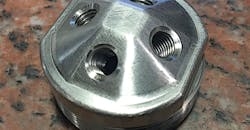
What exactly is computer-numerical-controlled (CNC) machining? It’s a means to make parts by removing material via high-speed, precision robotic machines that use an array of cutting tools to create the final design. CNC machines commonly used to create the geometric shapes required by customers are vertical milling machines, horizontal milling machines, and lathes.
To successfully make a part on a CNC machine, programs instruct the machine how it should move. The programmed instructions are encoded using computer-aided-manufacturing (CAM) software in conjunction with the computer-aided-design (CAD) model provided by the customer. The CAD model is loaded into the CAM software and tool paths are created based on the required geometry of the manufactured part. After determining the tool paths, the CAM software creates machine code (G-code) that instructs the machine on how fast it should move, how fast to turn the stock and/or tool, and the location to move in a 5-axis coordinate system.
Complex cylindrical shapes can be manufactured more cost-effectively using a CNC lathe versus a 3- or 5-axis CNC milling machine. With a CNC lathe, cutting tools are stationary and the part stock is turning, whereas on a CNC mill, the tool turns and the stock is fixed. To create the geometry, the CNC computer controls the rotational speed of the stock as well as the movement and feed rates of the stationary tools required to manufacture the part. If square features need to be created on a round part, the round geometry is first created on the CNC lathe and then the square features would be made on a CNC mill.
Because the computer controls the machine movement, the X, Y, and Z axes can all move simultaneously to produce a range of features, from simple straight lines to complex geometric shapes. Some limitations do exist in CNC machining, and not all shapes and features can be created even with the advances made in tooling and CNC controls. The limitations will be discussed later.
General Tolerances
If a drawing or specification sheet has not been provided by the customer, a company may provide general specifications to follow to manufacture a model. These specifications may change from one company to another. In addition, some companies do not have default tolerances and will require the customer to provide the specifications.
Listed below are the specifications Xometry follows when a customer has not provided any.
- Tolerance for all dimensions will be ±.005 in. for all metal parts and ±.010 in. for all plastic parts.
- The finish will be an as milled finish to a maximum 125 microinches RMS.
- If tapped holes are not added on the quote and a provided drawing, they will not be added to the part and will be machined to the diameter specified in the model.
- No surface treatment (bead blast, anodize, powder coat, etc.) will be applied unless specifically requested by the customer.
- For metal parts, walls should be a minimum 0.030 in. (~0.75 mm) thick.
- For plastic parts, walls should be a minimum of 0.060 in. (~1.5 mm) thick.
When the customer doesn’t supply specifications, Xometry follows its own set of specs.
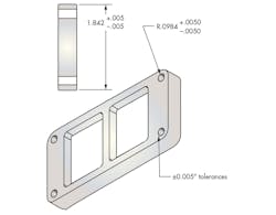
Part Tolerances
Tolerance is the acceptable range for a dimension, which is determined by the designer based on the form, fit, and function of a part. It is important to keep in mind that a tighter tolerance can result in additional cost due to increased scrap, additional fixturing, and/or special measurement tools.
Longer cycle times can also add to the cost if the machine needs to slow down to hold tighter tolerances. Depending on the tolerance call out and the geometry associated with it, costs can be more than double of what it would be to hold the standard tolerance. Tighter tolerances should only be used when it is necessary to meet the design criteria for the part.
Furthermore, overall geometric tolerances can be applied to the drawing for the part. Based on the geometric tolerance and type of tolerance applied, cost may rise due to increased inspection times.
The best way to apply tolerances is to only apply tight and/or geometric tolerances to critical areas, which will help minimize costs.
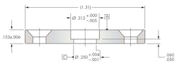
Unless specifically called out by the designer, the standard tolerance used by Xometry is ±.005 in. for metal parts and ±.010 in. for plastic parts. If tighter tolerances (less than the standard, e.g. ±.002 in.) are required, the information must be communicated as to which dimensions require a more narrow range. As a point of reference, a piece of paper is about 0.003 in. thick.
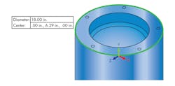
Size Limitations
Milling
Part size is limited to the machine’s capabilities and depth of cut required by a feature in the part. Keep in mind that a build space’s dimensions don’t equate to part size. For example, a Z travel of 38 inches doesn’t mean that a part can be machined to that depth or height (see below). Depending the on the part size and feature that needs to be machined, the Z height of the part will need to be less than the 38 inches because of tool clearance and depth of cut. The features and size of the part will determine the part’s machinable height.
Lathe
Lathe capabilities will depend on the build space, or the diameter and length (see below). A company may also offer a live tooling lathe, which dramatically decreases lead times and increases the amount of features that can be machined by combining additional CNC milling functions within the lathe.
Material Selection
Material selection is critical in determining the overall functionality and cost of the part. The designer must define the design’s important material characteristics—hardness, rigidity, chemical resistance, heat treatability, and thermal stability, just to name a few.
The material blank is the size of the material that will be used to create the finished part. For example, if the finished part dimensions are 3.5 in. long × 2 in. wide × 1 in. tall, then the material blank size in its raw form would need to be a minimum of 3.75 in. long × 2.125 in. wide × 1.125 in. tall. Material blank thickness is another area that should be considered during the design process.
A good rule to follow is to account for a blank that is a minimum of 0.125 in. larger than the part size. For example, if the final dimensions are to be 1 in. × 1 in. × 1 in., then the blank for the part would be 1.125 in. × 1.125 in. × 1.125 in. to allow for the variations in the raw material. When designing the part, consider if the form, fit, and function of the part would not be changed if the final part dimensions were 0.875 in. × 0.875 in. × 0.875 in. This way, a standard 1-in. x 1-in. x 1-in. block could be ordered and save some material cost versus a larger starting blank.
Metals
(The cost presented will vary depending on vendor.)
As a general rule, softer metals, like aluminum and brass, as well as plastics, machine easily and will take less time to remove material, which in turn reduces time and cost. Harder materials, like stainless steel and carbon steel, must be machined with slower spindle RPMs and machine feed rates, which would increase the cycle times versus the softer materials. As a general rule, aluminum will machine about four times faster than carbon steel, and eight times faster than stainless steel.
The type of material is a critical driver in determining the overall cost of the part. For example, 6061 aluminum bar stock is approximately half the price per pound of aluminum plate, and 7075 aluminum bar stock can be two to three times the cost of 6061 bar stock. Cost for 304 stainless steel is about two to three times that of 6061 aluminum, and about twice as much as 1018 carbon steel.
Depending on the size and geometry of the part, the material cost can assume a significant portion of the overall price of the part. If the design doesn’t warrant the properties of a carbon or stainless steel, consider using 6061 aluminum to minimize the material expense.
Plastics
(The cost presented will vary depending on vendor.)
Plastic material can be a less expensive alternative to metals if the design doesn’t require the rigidity of metal. Polyethylene is easy to machine, and costs about 1/3 that of 6061 aluminum. In general terms, ABS is about 1½ times the cost of Acetal; nylon and polycarbonate are approximately three times the cost of Acetal. Keep in mind that depending on the geometry, tight tolerances can be harder to hold with plastics, and the parts could warp after machining because of the stress created when material is removed.
Complexity and Limitations
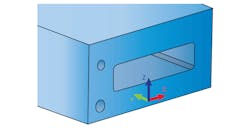
The more complex the part, which means contoured geometry or multiple faces that need to be cut, the more costly it is due to additional setup time and time to cut the part. When a part can be cut in two axes, the setup and machining can be accomplished faster, thus minimizing the cost.
For simple two-axis parts, more material will be removed as the tool moves around the part than with a contoured part. With a more complex part, some areas will need to be cut with X, Y and Z axes moving together.
To create a complex surface with a good surface finish, very small cuts will need to be used. This increases the time and, therefore, price of a part. A general rule to help minimize the cost is to try and design using only two axes cuts, but this isn’t always possible if a certain look or functionality is required. Keeping things consistent, such as internal corner radii and tapped holes, will also help save time and money on parts by reducing the need for tool changes.
Five-Axis Machining
Five-axis machining capabilities allow for more complex parts to be manufactured in the most cost-effective manner. Five-axis machining means that the machine and the part can be moved in up to five ways simultaneously around multiple axes. The coordinated movement allows for very complex parts to be manufactured more efficiently because it minimizes setups, attains faster cutting speeds, generates more efficient tool paths, and achieves better surface finishes.
By using five-axis technology versus conventional three-axis machining, fewer setups are required to create a part with complex geometry. With three-axis milling, contoured parts, or parts with machining on several faces require multiple setups to create the geometry. Oftentimes, with three-axis machining, complex fixtures must be made in order to hold a part in the orientation necessary to create the feature. Five-axis machining eliminates the need, and thus cost, of creating the fixtures, because the part can be held once and rotated to create complex geometries.
Five of the six faces can be machined (using five-axis technology) with one setup, which eliminates the cost and time to create four other setups to create the features. The part is set up once and the CNC machine rotates the part in the correct orientation to create the geometry.
Finally, by using a five-axis capable machine, the machine and part movement allows for the cutting tool to remain tangential to the cutting surface. Lower cycle times and costs are achieved because more material can be removed with each pass of the tool, and better surface finishes result by using the five-axis capabilities on contoured geometry. In traditional three-axis machining, very small cuts must be used to create a good surface finish, resulting in longer lead times.
Many other factors that will affect the cost, time, and ease of manufacturing. In Part 2 of this guide (coming soon), we will cover features such as fillets, undercuts, threads, and more.

About the Author
Voice Your Opinion!
To join the conversation, and become an exclusive member of Machine Design, create an account today!

Leaders relevant to this article: