Engineering Design Tools: A Look Back

Download this article in PDF format.
The job of an engineer hasn’t changed in the 90 years since Machine Design first published. The role is still to improve the performance and lower the cost of problem-solving devices, as well as the machines that make those devices. Over those decades, however, engineers have also played critical roles in changing the tools they use to do their jobs.
State-of-the-Art, 1929
An article in the first issue of Machine Design, “Organization and Supervision of Design Department”, discussed some of the basic engineering tools of the time. The most basic tool described is the office itself. It should be an “airy space preferably on a top floor,” perhaps to be far from distracting noises and with access to fresh air in those days before air conditioning. The article also recommends an open office, no other rooms, cubicles, or offices (except for labs), and easy access to the shops on the factory floor.
The article argues against geographically sprawling facilities which seem so much the norm today due to more advanced communications. “The physical separation of a design department located in a different city or town from the factory, convenient as it may be to a certain major general executive, is a severe handicap for any good design department to overcome.”
The design room should have “good substantial furniture” that creates a feeling of permanence and confidence. The article even considers interior decoration: framed photos of past projects and constructions, said to be well worth the cost in the company spirit they foster.
Technology wasn’t all that high back then. Indirect lighting won out over individual lights because the personal lamps needed constant readjusting and either gave too little or too much light.
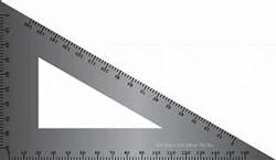
Some “old” tech was being replaced. For example, T-squares might still be useful, but the parallel rule attachment or universal drafting machines were more accurate, functioned more positively, and saved a great deal of time. Individual thumbtacks were being replaced by small machines for driving staples for fastening drawings down on drafting tables. OSHA might blush today, but the staples are said to be “removed readily by a knife blade.”
Another high-tech newcomer was the electric erasing machine for erasing ink. It was said to be a “great time saver and makes possible work that otherwise could not be done.”
Tables played a large role in those early design departments, apparently. The article notes that design firms handling any large projects need a few ”extremely large drafting tables” for large-scale layouts of complete machines. Each designer’s drafting table would optimally have drawers and covers to protect the work and keep it clean at night.
They needed a separate glass-topped tracing table (with lights) for retracing old drawings and blueprints. The drawing and prints could be attached to the glass with gummed stickers. And if you were going to work on the tracing table with a compass or dividers, adding a sheet of celluloid between the glass and the drawing would prevent damage to the glass.
The article also noted that the company should provide consumables, including pencils, easers, ink, drawing paper, tracing cloth, cross-section paper, thumb tacks, sandpaper, and pencil pointers. And it shouldn’t scrimp; buy the best.
There also were tools stored at some design firms, depending on what kind of engineering jobs they tackled, and the engineers staff used them on an as-needed basis. These included beam compasses, splines and spline weights, ship and railroad curves, proportional dividers, planimeters, a surface plate, and large protractors. Calipers; micrometers; thread, radius, and height gages; and surveying equipment also came in handy.
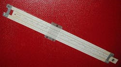
Engineers were expected to show up with a well-stocked toolbox. It included a good set of mechanical drawing instruments, triangles, rules, slide rule, and handbooks.
The Material Age
Though not traditionally considered tools, new materials gave engineers in the 1930s and ’40s an arsenal of plastics and alloys to lower weight and cost in cars, airplanes, and household appliances without losing performance or good looks. Lead-bronze and cadmium-silver copper, for example, now provided auto engineers with some heat-resistant metals for rods and bearings.
Fibers from cotton, asbestos, phenols, and rubbers (synthetic and natural) all found uses in various machine components and manufacturing processes. As noted in a 1935 Machine Design editorial: “For many years, engineers have considered plastic materials as being suitable only for ornamentation or insulation. But that day is passing.”
To aid its engineering audience, Machine Design decided to publish a “complete listing of domestic materials of this type” (nonmetallic) in 1935. Those three pages contained 62 materials, from Ace, a hard rubber used in cars and X-ray equipment, to Vulcoid, a laminated fiber good for insulation. That was the start of the Materials Directories the magazine continued to publish into the 1990s as the metallic and non-metallic materials available to engineers continued its expansion.

Speed and Analysis
As engineers successfully plied their craft, machines started spinning and moving faster and faster to speed production. In fact, they got so fast, no one could see exactly what was happening when there was a failure or misalignment or some other upsetting incident on the line.
At first, simple stroboscopes were used to freeze action in still photos. But the accidental motion or misstep was impossible to freeze when engineers didn’t know exactly when it occurred.
This was the situation when one textile company in 1935, the Crompton & Knowles Loom Works, was switching over to rayon. The shuttle and the mechanisms that separated the threads were not behaving and all the rules of thumb collected over years of working with automated looms and cotton threads were unhelpful. And stroboscopic photos never seemed to catch the shuttle when it was misbehaving.
To get a good look at what was going on, engineers took film running at 188 frames per second with exposure of 1/20,000th of a second. To make the images bright and clear with such short exposure times, they lit up the loom with 17 arc lamps drawing a total of 350 amps at 110 V.
Careful study of the film showed engineers that the shuttle was not slowing down at a critical point and needed some extra measures to keep its speed under control. The editorial in that issue talks about the role high-speed film could play in engineering. “The motion picture camera has played a large part in the lives of everyone; it may well play a still more important part, in another role, in the lives or engineers responsible for design.”
War Dividend
World War II supercharged engineering in the U.S. New technologies, especially in the electrical and electronics fields, were changing the devices engineers worked on. Designers were as likely to work with voltmeters and an oscilloscope as a gears and cams. Engineers also learned a lot about their own profession when pushed by the war to constantly come up with better planes and ships, as well as better ways to make them.
For example, the B-29 Superfortress bomber took 157,000 man-hours in 1942 to assemble from its 55,000 numbered parts (not including rivets and other small parts). By 1945 that was down to 57,000 man-hours, and the ultimate goal was 30,000 man-hours. Endurance testing of alloy turbine blades once took five to six years to gather all the data. Accelerated testing in 1945 got that data in a month.
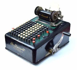
There were adding machines and other mechanical calculators used in the 1940s, even ones that could solve differential equations. But manual calculations and the slide rule handled most computations. And many engineers relied on tables and charts of important design data and rules of thumb they had gathered over the years, some from the pages of Machine Design.
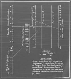
One clever tool, the nonmogram, let engineers and others quickly solve specific problems they often ran into. The graphical calculator in its simplest form consist of three vertical scales. Line up two known variables on the far left and far right scales, and the line drawn between them crosses the middle scale at the solution of the problem.
Like a slide rule, the user had to interpolate the answer, but if an approximate answer will do, the nomograms work fine. They have been written for a wide variety of purposes, including for designing channels and pipes for controlling the flow of water; calculating ballistics for firing weapons when time was critical, and not all soldiers handling the weapons were trained in ballistics; and even by the Soviets to calculate the orbit of Sputnik 1 (see figure).
Another tool that was used mainly in the 1950s through the 1970s was photoelasticity. It let engineers see stresses in various shaped parts. It took advantage of the fact that some transparent materials, such as glass and plastic, become doubly refracting under stress. So subjecting photoelastic materials to pressure creates internal strains that can be seen in polarized light.
Engineers took advantage of this property by making a plastic cross-sectional model of a design—a gear beam, or bracket support, for example. Putting pressure on the top and bottom of the model makes stressed areas change colors (called fringes). This let engineers see stress distributions and concentrations around discontinuities such as holes punched in the components or sharp corners. With stress concentrations correlated to crack formation and other defects, designers could try to “design out” the discontinuities to come up with a stronger component.
But the technique was long and tedious and yielded qualitative stress readings rather than hard numbers. Engineers also had to choose a cross-section of the component being studied and make a model of it. THis found limited use in industry and education. Engineers on high-end projects such as airliners and space craft do use it to validate Finite Element Analysis (FEA) model stress.
The Rise of the Computer
Once computers caught on and chipmakers become proficient at their tasks, the change in computers from mainframes to workstations to desktop PCs to laptops was astounding. They went from rare to one—maybe two—on every desk. Cost plummeted while performance continued climbing. It’s the one tool (if you count hardware and software together) for engineers that engineers have spent the most time and expertise in upgrading and advancing.
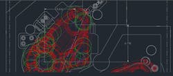
As a result, engineering tools have been computerized. Primary among this group is mechanical drawing. Though it was at first limited to deep-pocket DoD projects and airliners, practically every engineer has some form of computerized drafting software for designing and getting parts made on the factory floor.
Computerized drafting has also advanced, moving to two-dimensional, three-dimensional, and finally solid modeling. Modeling also expanded into rapid prototyping, an automated twist on the practice of prototyping that has been going on for a long time in engineering, most famously with life-sized wax versions of the new cars and trucks designed over the years. Rapid prototyping is now trying to get established more as a manufacturing method rather than an engineering design tool.
Modeling also expanded into FEA as computational power became cheap enough to analyze models made up of millions of individual cells or bricks. FEA now looks at the structural dynamics, thermal behavior, vibrations, fluid flow, and electromagnetic potentials of new designs before an metal is cut or machined.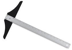
A computer-based analysis similar to FEA in its reliance on inexpensive computer power is computational fluid flow (CFD). It uses numerical analysis to look at fluid flow, which includes aerodynamics and the problems of transonic and supersonic airflow over aircraft wings and airfoils. In fact, initial validation of CFD software routinely takes place in wind tunnels.
CFD is used in a wide range of research and engineering industries, including aerodynamics and aerospace analysis; weather simulation; natural science and environmental engineering; industrial system design and analysis; biological engineering and fluid flows; and engine and combustion analysis.
About the Author
Voice Your Opinion!
To join the conversation, and become an exclusive member of Machine Design, create an account today!

Leaders relevant to this article: