Step motors are popular first and foremost because they are easy to use. They do not require an encoder to maintain their position, and unlike DC brush or brushless DC motors when used for positioning, they do not require a servo control loop. Their advantages are low cost, high torque output and brushless operation. However, they also have significant drawbacks which include vibration, noise and a limited speed range.
A new drive technique called closed loop stepper, also sometimes called stepper servo, is starting to gain attention because it can address many of these classic step motor problems and at the same time can actually extract more performance out of the motor. In some applications step motors driven with the closed loop stepper method outperform brushless DC motors in the important categories of acceleration rate and torque output per unit weight of the motor.
The crux of closed loop stepper operation is adding an encoder and operating the motor as a commutated two-phase brushless DC motor. The fact that an encoder is needed means that truly low-cost applications will not be good candidates for closed loop stepper. But closed loop stepper do represent a powerful alternative to traditional step motors drive schemes.
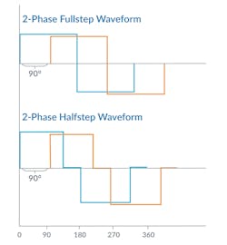
Figure 1 shows traditional waveforms for driving a step motor. Step motors are a multi-phase device, meaning multiple motor coils are electrically excited to create motion. Step motors are usually constructed with 1.8 mechanical degrees per full step (90 electrical degrees). This means a 1.8-deg. stepper has 200 full steps per mechanical rotation. In addition to 1.8-deg. step motors, other configurations exist such as .9 and 7.2 deg.
Magnetics Drive the Motor
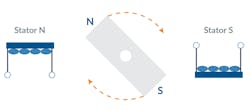
Let us look at what's happening inside the motor to understand in more detail how a traditional step motor is operated.
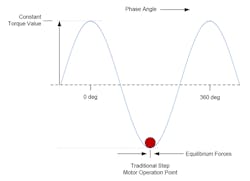
Figure 2 provides a simple magnetic model of a step motor. The rotor can be thought of as a spinning bar magnet that interacts with an externally controlled magnetic field (the stator). The rotational torque generated is zero when the N-S rotor field aligns with the stator N-S magnetic field (also called a B-Field), and at its largest when the two fields are at an angle of 90 electrical degrees from each other. Note that although the actual internal construction of a step motor looks nothing like this, it is still a useful way to understand the motor operation.
When the motor coils are driven with current a sinusoidal force “valley” is created which drives the step motor to settle at a specific position. The more current that is driven through the coils, the greater the depth of the force valley and the greater the holding force on the motor. In this profile of hills and valleys, wherever the curve is horizontal there is no mechanical torque generated, and wherever the curve is the steepest, the generated torque is the largest.
As Figure 3 shows, in a traditional step motor drive scheme the motor settles to the “bottom” of the force profile. At this point the net motor torque generated is zero because the motor is at an equilibrium point. This explains why position can be maintained in a step motor without an encoder or servo loop.
To create motion, the controller moves this valley forward or backward by changing the motor’s phase angle via the external coil connections. When the electrical vector changes the motor rotor “falls” forward or backward, maintaining itself at the bottom of the force valley in response. Think of a ball settling to the bottom of a trough. While convenient and simple, this scheme has several drawbacks including vibration and a related phenomenon called mid-range instability. Why does this control scheme have so much vibration?
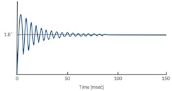
The answer stems from the fact that the rotor position settles to an equilibrium position but is not actively held in that position. This means the rotor’s inertia as well as any outside forces that may exist will cause the motor to deflect from the equilibrium position. Figure 4 provides an example of this, showing how the rotor rings and takes time to settle when commanded to move to the next full step.
Normally we think of ringing and settling such as this a servo loop phenomenon, but if you think about the ball settling in a trough it starts to make sense. The phenomenon of mid-range instability occurs when this ringing frequency equals the commanded step rate. In this condition the ringing and the step rate reinforce each other and cause a resonance that reduces the available torque at a specific speed—or worse, results in the motor losing steps or the motion entirely coming to a stop.
Actively Controlling the Rotor Position
Closed loop stepper operation is different in three key ways:
- It requires an encoder to be attached to the step motor, one with a fairly high resolution. For standard 1.8-deg. step motors you will want an encoder with no less than 2,000 counts per mechanical rotation, and for 7.2-deg. step motors 500 is a bare minimum.
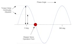
- The motor is operated like a brushless DC motor and commutates the phase angle using the actual encoder position rather than the commanded position. Redrawing our force diagram, Figure 5 shows how commutated phasing means the step motor operation point is shifted by 90 deg. to the steepest part of the force valley rather than at the equilibrium point.
- Instead of being constant, the height and phase angle of the waveform are continuously varied based on the output of a position PID loop, which is used to servo on the commanded position. Again, this is the same as how a brushless DC motor is operated.
There are many advantages to operating a motor ion this way:
- No lost steps. One immediate advantage is that losing steps is no longer a concern. Operated as a servo motor, the encoder determines the location of the step motor. Consequently, the problem of losing steps—an ever-present worry in traditional step motor applications—no longer applies.
- Less heat. Another advantage is that a closed loop stepper, because it uses a servo drive technique, outputs just the amount of torque needed to achieve a desired motion profile. Traditionally controlled step motors are driven at a constant current that must be sufficiently large to handle the worst-case motion profile, and this excess current generates heat.
- Accuracy. Since the encoder is used to drive the location of the motor, the positioning accuracy becomes unlinked from the motor’s step resolution. Therefore, the same motor could achieve 2,000 resolvable locations per rotation or 1,000,000 resolvable locations depending only on the encoder used.
- Noise. With a closed loop stepper technique, the motor generates much less noise than a full step or half step drive, and even less noise than a microstepping drive. While not as quiet as a typical brushless DC motors, closed loop stepper pretty much kills the classic step motor noise problem.
New Control Scheme Needed
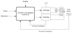
Figure 6 provides an overview diagram of a typical closer loop stepper connection scheme. At this high level, the system diagram doesn’t look that different from a traditional step motor scheme, other than the inclusion of an encoder.
But the internal control scheme used with closed loop stepper looks quite different than a traditional step motor control scheme. This scheme, shown in Fig. 7, has three overall elements: a position PID loop, a current loop and a switch mode amplifier.
The PID loop inputs a commanded position, either from an external pulse & direction source or an internal profile generator and uses the measured encoder position to generate a current command after passing through a PID filter. Next, this current command must be commutated. This can be done using a sinusoidal lookup table, or in more sophisticated controllers by a technique called FOC (Field Oriented Control). Although in the diagram above only one current loop is shown, in fact separate current loops are used for each motor phase.
Finally, digital switching bridges, each consisting of four switches in an H-Bridge configuration, drive the motor coils from the +HV supply. The switch circuitry is arranged so that the current in each motor coil can be measured and fed back to the controller to execute the current loops.
Is Closed Loop Stepper a Good Choice?
Although closed loop stepper control has been on the scene for more than 10 years, it is only in the last few years, with the availability of cost-effective and high-resolution encoders and dedicated low-cost closed loop stepper ICs, that this technique has started to see more widespread adoption.
Although not a match for every application, without question machine designers should be aware of what the closed loop stepper control scheme can offer. It is one of the most important developments in motion control of the past decade, and has the potential to provide higher performance at a lower cost in some applications when compared with brushless DC motors.
Chuck Lewin is CEO and founder of Performance Motion Devices, Inc.
