Use RDT for Miniature DC Gearmotor Life Projections

Motion control solutions that deliver high power density in a small package can add value in a broad range of applications—including industrial power tools, surgical instruments, robotics, aerospace and defense. Gearmotors can deliver on that power density in these applications and more.
A DC gearmotor is an assembly of a brushed or brushless DC motor and a gearbox that specifically fulfills an application’s torque (mNm), speed (RPM) and efficiency (%) requirements. By adding a gearhead to the motor, the output speed is reduced while the torque is simultaneously increased. Gearmotors play an important role in applications, given that they can attain comparatively higher torque than an individual motor in a smaller diameter with additional length.
In addition to attaining torque, speed and efficiency requirements, reliability is a fourth crucial parameter for many applications. This means that miniature motor suppliers must ensure their motors meet certain reliability targets. This is where Reliability Demonstration Testing comes in.
Reliability Demonstration Testing Explained
Reliability Demonstration Testing (RDT) as been widely used in the manufacturing industry to verify whether a product has met a certain reliability requirement with a stated confidence level. This is a pass/fail test that is usually performed at a system or product level. The RDT process can be divided into three stages: planning, testing and monitoring and data analysis.
READ MORE: Physical Testing is Alive and Well Throughout the Engineering World
Stage 1: Planning
The reliability goal is first set in the planning stage—such as the reliability at a specific time with a given confidence level. At this point, the plan for RDT can be structured. Once the reliability goal is set, the next step is to select the distribution and acceleration models to calculate the sample size, the test time for required reliability and the confidence level. Without a reliability target, the RDT parameters cannot be planned.
An important step in this stage is to select a statistical model to estimate the sample size and test time. Non-parametric binomial models and parametric binomial models are most commonly utilized for RDT:
- Parametric binomial models are used when the test duration differs from the time of the required reliability. An underlying distribution, such as Weibull, should be assumed.
- Non-parametric binomial models can be used for one shot devices, as no distribution assumption is needed.
Stage 2: Testing and Monitoring
In the testing and monitoring stage, the RDT is performed, with the gearmotor’s performance being monitored daily. Performance monitoring includes measurements of voltage, current, speed, temperature and visual inspection for any abnormal noise or physical damage.
Stage 3: Data Analysis
In the final analysis stage, the testing data is compiled and a report is written based on the results. The report will compare the achieved results to the goal and outline how the data was calculated. If a few samples fail during the test, the failure data can be analyzed with the Weibull method to calculate the achieved reliability.
However, the goal for RDT is to demonstrate the reliability without failure at the specified time, which is also known as a zero-failure test. The required test time will be recalculated if any failure is observed before the targeted test time is reached.
READ MORE: How to Protect Your Powered Surgical Tools from Moisture and Corrosion
Note: RDT can be completed under both the actual application condition—which is always recommended—as well as under accelerated stress conditions. However, when the required time for the reliability target is very high, such as a B10* life of 10 years, the accelerated life test method can be used to shorten the test time to complete the first-level data. An accelerated life test on a gearmotor can be performed using certain stresses like power, torque, speed, temperature, etc.
*B10 life is the time at which 10% of units in a population will fail. This can alternatively be thought of as the 90% reliability of a population at a specific point in its life, or the point in time when an item has a 90% probability of survival.
Reliability Demonstration Testing in Practice
A medical device manufacturer developed an infusion system and engaged the motor supplier to validate the reliability of the DC gearmotor via RDT. In this case, the supplier needed to validate the B10 life (hours) at a 95% confidence level. As the required B10 life was significant at 10,000 hours, which is over a year of actual run time, the reliability engineer decided to perform the RDT in an accelerated manner.
Acceleration Factor Calculation
The gearmotor’s life is primarily dependent on the applied load and application conditions. The engineering team chose “torque” at constant speed as the stress for accelerating the testing time, while the reliability and testing team utilized the inverse power law (IPL) model to calculate the acceleration factor (AF) to reduce the test time.
The IPL model, or relationship, is commonly used for non-thermal accelerated stresses such as voltage, current, mechanical load, torque, speed, etc. The acceleration factor calculation model used is:
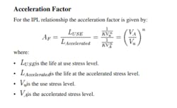
The parameter “n” in the inverse power relationship is a measure of the effect of the stress on the gearmotor’s reliability. As the absolute value of n increases, the greater the effect of the stress. Based on previous experience of gearbox testing, n is assumed to be 3 for the worst-case scenario.
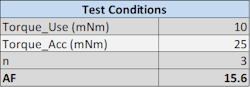
In the medical device application, the gearmotor’s torque requirement was 10 mNm. For the acceleration factor calculation, the torque for accelerated stress was selected at 25 mNm, with a constant speed of 200 rpm, as specified by the application.
Based on the above formula for inverse power law, the stress values in the above table—which used level torque and accelerated level torque—and the stress factor n, the acceleration factor is calculated as 15.6.
Test Time Calculation
After the calculation of the acceleration factor, the test time was calculated using the parametric binomial method. Using a parametric binomial equation for sample size calculations from “Design of Reliability Tests” by Reliability Hotwire, one can see that:
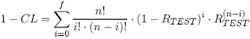
where:
- CL = the required confidence level
- f = the allowable number of failures
- n = the total number of units on test
- RTEST = the reliability on test
The binomial method calculates the test sample size required to demonstrate a reliability value at a given confidence level. The parametric binomial method makes use of the Weibull distribution to define the reliability (R) in the above binomial equation. Given a reliability requirement (R) for a mission time (T), and a value for the Weibull shape parameter (β), the Weibull reliability function is solved for characteristic life (η). This fully defines the Weibull reliability function and allows for the calculation of reliability at any other point in the reliability curve.
READ MORE: Getting the Right Stepper or Servo Motor for Electric Actuators
Assuming a Weibull distribution beta value of 2 for wear-out failure, the sample size was chosen as 10 and the required test time was calculated.
This equation can be further modified by using the reliability equation for Weibull distribution. The calculation can be done directly with Weibull++ software, with a given target reliability of 90% (B10 Life), 10,000 hours, 95% confidence level, zero failure criteria and a sample size of 10. This was decided as per testing feasibility.
The required test time is calculated as 1,081 hours considering zero failure cases, meaning all 10 samples being tested needed to complete 1,081 hours without a single failure.
Testing
Once the testing plan was completed for the 10 gearmotors under stressed conditions, the next step was to execute the test plan. To perform the test, the 10 gearmotors and test instruments were set up on the test bench. This required a power supply, test fixtures, couplers, brakes, a wiring harness, a multimeter and a torque gauge. The required torque level was maintained using hysteresis brakes and torque limiters.
Functional testing on each motor was performed before the RDT test. No load performance was completed on all motors to ensure that the performance of each motor was within specification. During the RDT test, various performance parameters of the motors—including voltage, current, speed and temperature—were recorded daily.
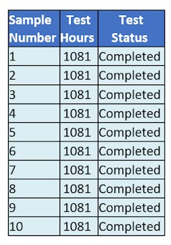
In this case study, all 10 motors completed the required test time of 1,081 hours without failure. No abnormalities were observed in any motor; therefore, the required B10 life of 10,000 hours with 95% confidence level was validated through the test.
Summary
The systematic approach of reliability demonstration testing helps to illustrate the target reliability of DC gearmotors used in different applications, such as the medical infusion systems application reviewed above. The paper also reviewed the RDT method to demonstrate gearmotor reliability through accelerated life testing. Because the testing period under normal operating conditions may take several months to complete, the accelerated life test method helps to reduce the time investment and sample size while ensuring that the gearmotors meet the required reliability at the desired confidence level.
Utpal Rabha is a lead reliability engineer at Portescap.
About the Author
Utpal Rabha
Lead Reliability Engineer, Portescap
Voice Your Opinion!
To join the conversation, and become an exclusive member of Machine Design, create an account today!

Leaders relevant to this article: