VFD Cables Stand Up to Pulse Width Modulation Hazards and Harsh Conditions
When an application requires changes in motor speeds to meet its objectives, a variable frequency drive (VFD) is often the first thing that comes to mind. This is for good reason—VFDs are typically the most efficient, economical and energy-saving method available. However, the same characteristics that make VFDs an attractive choice for motor speed control make conventional cables prohibitive in many systems.
Without a cable constructed specifically for VFD applications, equipment will be prone to various threats that can lead to premature failure. Here are the construction features to look for in a VFD cable, and some tips and best practices to ensure successful implementation.
VFD Fundamentals: An Overview
A typical VFD drive turns an AC motor’s current into a direct current (DC) signal that replicates a sine wave. The incoming alternating current (AC) passes through a series of diodes which convert the AC into DC voltage. This is then stored, filtered and sent to the drive’s inverter section. Transistors inside the inverter rapidly switch the output voltage in a sequence set by the controller—a process known as pulse width modulation (PWM). This defines the output AC frequency. The varying frequency of the high-voltage output allows the motor to start and stop or to accelerate and decelerate.
As a result, high-power PWM signals in a VFD system create several conditions that can overburden conventional cables and ultimately damage machinery. These include reflected waves, corona inception voltage, common mode currents, EMI/RFI and extreme heat. Besides these energy-related threats, VFDs are often situated in harsh industrial environments.
READ MORE: GFCI-Protected Circuits: Don’t Get Tripped up by VFDs
VFD Cable Construction Elements
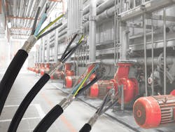
Cable vendors such as SAB North America offer cables specially constructed for VFD applications. VFD cables typically have a copper or tinned copper conductor due to the metal’s high conductivity and low resistance. These conductors are typically flexible, so the cable can withstand bending motions common in industrial applications without incurring signal losses. Cable selection criteria should also include the jacketing materials used to protect the cables against harsh conditions.
Cable sizes for VFD applications can range from 500 KCMil to 18 AWG. But when it comes to the essential elements of a cable, the insulation material sets VFD cables apart from traditional cables. Following is an overview of various conditions that can harm VFD cables, along with the insulation features to look for in a VFD cable to ensure a long, reliable lifetime:
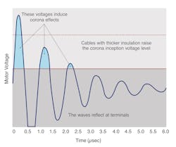
- Reflected waves. A mismatch of impedances between a VFD’s motor and its cable can cause frequency waves to bounce back to the drive. When this occurs, the insulator can break down and overheat the cable.
- Corona inception voltage/corona discharge. Voltages in VFD systems can vary greatly, oscillating from zero to peak voltage. When there’s a spike of high voltage, air around a local electric field becomes ionized. This corona discharge can melt insulation and damage cables.
To address these issues, one option is to use a PVC-insulated cable with greater thickness than prescribed by National Electric Code (NEC) standards for THHN wire in conjunction with a high-heat nylon thermoplastic. However, the NEC has changed its guidelines stating that PVC-based conductors are no longer permitted for use in VFD applications.
Cross-linked polyethylene (XLPE) is now the recommended insulation material for VFD cables, per NEC. With lower capacitance ratings than PVC, XLPE minimizes charging currents, provides better heat resistance and offers protection against corona discharge. Lower capacitance is a particularly important characteristic for longer-length cables since long runs can also create reflective waves. For these reasons, VFD manufacturers often suggest cable with core insulation thickness of 32 mm or greater of XLPE insulation.
Consider for example SAB North America’s range of reliable UL- and CSA-listed VFD cables designed to minimize downtime and provide long life for drives and system equipment used in automation applications. The cables come with XLPE insulation rated for RHW-2 and XHHW-2, making them compliant to the NFPA 79 code, 2018 Edition. SAB VFD cables carry NEC TC-ER ratings, indicating that the cables can be installed with or without a cable tray.
READ MORE: Low-Voltage DC Drives for Battery-Powered Motion Control
Shielding and Grounding
Not only must VFD cables provide effective insulation, but they also have to mitigate common mode currents as well as electrical noise. Here’s why:
- Common mode currents. In traditional power supplies, the sum of the waveforms of the three phases is zero under normal conditions. VFDs, however, create three-phase voltages that do not equal zero, creating a voltage imbalance at the winding junction of a star-wound motor. When the non-zero voltage level changes, a proportional cable charging current returns via the grounding conductor. A high common-mode current can create ground loops that cause problems for various system components.
- Transmitted electrical noise. VFDs produce constantly changing frequencies, which can induce electromagnetic (EMI) and radio frequency interference (RFI) and affect nearby components and systems.
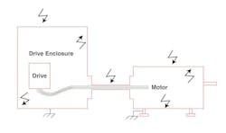
Under high-voltage conditions, high common-mode currents can go towards the motor and through the stator, causing the stator to fail and damage the system. To address common mode and EMI/RFI problems, make sure cables have robust shielding. They also must have a grounding path where the cables connect to both the drive enclosure and the motor.
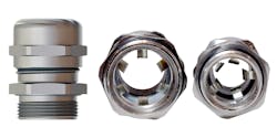
One conventional grounding method is to provide a 360-deg. contact at each entrance while pigtailing the shield to the PE terminal on the drive. EMC glands and shielded cables are well-suited for these connections. VFD cable manufacturers offer a variety of shielding options such as copper tape or foil and tinned copper braiding and cable glands, to name a few. Consult your cable manufacturer to help select a low-impedance shield and an EMC cable gland for the application.
Many shielded VFD cables include a drain that can be terminated to the second PE terminal on the drive and on the motor. Although the drain has some copper mass, pigtailing the tinned copper braid shield provides much greater copper mass to sufficiently drain the noise and create a ground path. Also, consider the size of your motor. Some motor manufacturers recommend cables that arrange the three phase leads and three earth conductors symmetrically. With a properly grounded enclosure and motor, you’ll create a Faraday Cage effect with constant voltage around the enclosure.
Jacketing
VFD cables also provide a rugged jacket to protect the cable against harsh industrial conditions like high temperatures that can break down other cables, as well as damp, dry or wet conditions; oil; corrosion; impacts; and sunlight. That’s why VFD cable jackets are typically made from specially formulated PVC. This thermoplastic material provides good mechanical strength, moisture resistance, light weight, long life and cost-effectiveness.
Specially formulated PVC is optimal for delivery of ideal properties to the application environment. For example, SAB VFD cable jackets are made from a special black PVC that is formulated to resist sunlight, oils and chemicals.
VFD Cables Offer Invaluable Protection Against Harsh Conditions
In addition to providing VFD cables with robust insulation and oil- and flame-resistant PVC jacketing, the SAB VFD cable lineup features a foil and tin copper braid shield for 100% protection against EMI from spikes, harmonics and power distortions. VFD cables also carry NEC Class 1, Div. 2 classification for use in hazardous locations. Highlights of the VFD cable offering include:
- VFD XLPE TR/VFD XLPE TR D, which comes with or without an integrated drain wire.
- VFD Symmetrical XLPE TR, with three phase leads and three symmetrical tinned copper grounds to minimize the risk of motor failure from common ground current.
- VFD Combo XLPE, with one or two pairs for temperature sensing or braking. Multiple pair AWGs are available.
- VFD XLPE 2 KV TR, a sun- and flame-resistant VFD cable rated up to 2,000V.
- Cable glands and termination kit. The cable glands come with built-in grounding mechanisms that contact the cable shield to provide effective EMC protection plus protection against impacts and vibrations. A termination kit is also available for grounding a shield to a metal enclosure.
Although conventional wires and cables can address a wide range of applications, VFD cables are constructed to address a host of conditions that can potentially harm VFD equipment and systems. Among available cable options, knowing which features to look for will ultimately help deliver the assurance manufacturers need for their VFD applications.
This article was submitted by Rick Orsini, product manager, SAB North America. Click here for more information on SAB North America VFD cables.


