Calculating bellows-coupling stiffness
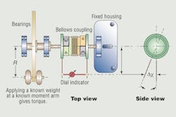
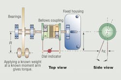
On faster servo systems even small power-train flexibility variations can compromise positioning accuracy. While many factors are involved, the stiffness of couplings has huge effects. That’s why metal bellows couplings are often used in servo systems: They possess high torsional stiffness without sacrificing misalignment compensation. Still, popping these couplings into systems is no longer a cure-all. This is a torsinal test setup for a bellows coupling:
Today’s rapid starts, stops, and directional cycling are pushing the limits of bellows coupling torsional stiffness — something unusual even ten years ago. For example, the couplings might appear in circuit-board drilling machines to connect servomotors and leadscrews used for microsecond-positioning of 1,000-lb masses. Only if properly specified can bellows couplings quicken settling time (sometimes by 50% for a 10% improvement in throughput.) For that, it’s important to know exactly how much torsional stiffness a coupling really has.
Q: Can a bellows coupling be too stiff for an application?
A: Stiffness should never be avoided — only misalignment. However, this gets back to the misalignmentcompensation issue. Bellows couplings are great at delivering on both stiffness and forgiveness, but there is always a tradeoff. Though machining is very accurate today, component tolerances stack up to compound overall system inaccuracy. Misalignment especially effects systems when centering from one diameter to another across a distance, emphasizing the need to observe safe lateral misalignments — from 0.1 to 0.2 mm for most couplings.
Q: How can a designer make sense of published torsional stiffness ratings when they are inconsistent from one manufacturer to the next?
A: Making direct comparisons between products can help designers better select the optimum coupling, and a simple test setup is one way to do it. An end of a bellows coupling is attached to a fixed housing, while the opposite end is attached to a freely moving beam moment arm. A dial indicator attached to both ends measures torsional deflection under varying loads to return overall stiffness. (This includes the effects of bellows and end hubs.) Then measurements can involve different masses to model rated torque values. Results do vary with fixture design and how operators perform actual test runs, but the real importance of these numbers is that they allow “apple to apple” coupling comparisons.
Q: How is stiffness quantified?
A: Torsional stiffness is a measurement of torque per angular displacement, and is expressed:
Where M = torque, Nm
Ψ = angular displacement, rad
By applying a known mass at a known moment arm, torque is:
Where m = mass, kg
g = Gravitational acceleration, 9.81 m/sec2
R = Moment arm, m
Angular displacement is determined from the dial indicator reading:
Δx = indicator reading, mm
τ = indicator moment arm, mm
Ψ = arctan (Δx/τ), deg
Torsional stiffness is computed:
Ct = M/c, N-m/deg
Ct = M•180/p x c, N-m/rad
From there the mass, moment arm, and measured dial indicator readings used in the equations return torsional stiffness values.
Tips provided by Gam Enterprises Inc. in Chicago. For more information, call (888) 426-7117.
About the Author
Elisabeth Eitel
Elisabeth Eitel was a Senior Editor at Machine Design magazine until 2014. She has a B.S. in Mechanical Engineering from Fenn College at Cleveland State University.


