Disturbance rejection for reliable motion output
Control systems are typically designed to encounter a set profile of forces. However, in real-world applications, they also experience unanticipated forces—disturbances impossible to model in advance. In the presence of these external disturbances, the control system must accurately track setpoint changes and correct output with sufficient speed.
A common method for disturbance rejection is a disturbance observer, which estimates a disturbance and rejects it without affecting performance.
A disturbance-observer control function makes real plants behave like the nominal plant for a certain frequency range—in turn, boosting system robustness. Another disturbance-observer characteristic that’s beneficial to design engineers is that its control functions can be developed at a design stage independent of that for overall controller design.
Integral control is currently the prevailing method. In fact, to both remove steady-state positioning error and cancel out the influence of external disturbances to motion control systems, the disturbance observer control function could soon become a common substitute.
Disturbance observer design
In other words, the fundamental function of disturbance rejection is to estimate real-time variations in the parameters and compensate for them online within a certain range. For a second-order motor control system:
Normalizing the disturbance torque with respect to input:
Therefore, a general form of the second-order plant for most motion control systems is given by:
Where Position x = Plant output
u = Control input to the plant
F = Force.
Control input gain b = 1/Je is inversed inertia load; the function f represents the remaining terms — disturbance — in the differential equation.
The key to disturbance-observer control-function design is to interpret disturbance f as an additional state variable of the dynamic system. For a second-order system, the number of states now increases from two to three, and the regular second system dynamic mode is:
Where L = Observer gain—which can be obtained using any known method—including the pole-placement technique.
Here, the system model’s closed-loop poles in the feedback control system are strategically placed—as the pole locations correspond to the system eigenvalues that shape system response.
The states of the observer correspond to the estimated values of:
Which yields the estimate for disturbance x3 = f, x1 as the targeted estimation for position, and x2 as the targeted estimation for velocity.
The above procedure can be further customized to a simplified format for a range of industrial applications at the cost of losing a certain degree of accuracy. For the simplified disturbance observer, a function Κ is used to impose limits on the disturbance estimation:
Therefore, estimated disturbances are always kept within the predetermined bounds: These predetermined bounds should be carefully chosen and the designer must ensure that they don’t deteriorate system stability — by constructing a Lyapunov function that includes the disturbance limitation.
Refer to Fig. 2. As expected, a system with a disturbance observer can eliminate steady-state error caused by a step disturbance at steady state. Similarly (as shown in Fig. 3), the system can eliminate a steady-state error caused by changing the system model through a ramp-tracking process. The system at startup catches up with the ramp setpoint. It can also eliminate steady-state error caused by disturbance.
Fig. 2: For this step response, system input = 1, and disturbance = 2 at 10 sec.
Fig. 3 left: At system startup, the control catches up with the ramp setpoint.
Fig. 3 right: The system can also eliminate steady-state error caused by disturbance.
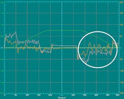
First, both the disturbance observer and integral control are turned off. Then the system is accelerated and decelerated.
As expected, there is steady-state error (circled in white). The yellow line is the commanded position; the green line indicates actual position; the brown line shows the following error, and the pink line represents the control output.
In Fig. 5, the disturbance observer is turned off. Integral control is turned on.
The steady-state error can be removed — but at the cost of bumpy following performance and a system stability violation caused by integral windup.
In Fig. 6, the system is accelerated and decelerated with a disturbance observer applied.
The yellow line is the commanded position; the green line indicates actual position; the brown line shows the following error, and the pink line represents the control output.
Steady-state error is removed, and following performance is smooth and controllable.
For more information, call (800) 358-9068 or visit parkermotion.com. Also read this author’s last article on sensorless vector control.
