Servocables: Combining power and feedback while mitigating noise

One of the golden rules in wiring servomotors is to separate the power and feedback cables. Otherwise, power conductors near feedback conductors degrade data transmission by inducing noise in the form of electromagnetic interference (EMI) and crosstalk. But like a lot of equipment, servomotor-driven machines are becoming smaller to cut costs. With space inside such machines decreasing, snaking multiple cables through them is becoming increasingly difficult — and adding more cables increases the risk of failure due to flexing.
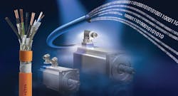
That’s why servocables, sometimes called composite or hybrid cables, are becoming more popular. These cables contain bundles of copper wire acting as conductors that transmit power, as well as conductor pairs that send power, temperature, and feedback signals to and from sensors.
Properly specified hybrid servocables supply sufficient electrical power to the motor at the right voltage — 480, 600, or 1,000 V for example. They also transmit feedback signals without garbling the data, even though noise-inducing power conductors run side by side the signal conductors. Hybrid servocables simplify connecting encoders and other feedback devices to servomotors and controllers. Finally, servocables meet regulatory guidelines and withstand the machine’s environment and modes of motion.
Four features to prevent signal loss
Like traditional feedback cables, hybrid cables transmit analog or digital signals to controls from feedback devices such as temperature and position sensors, encoders, and limit switches. The trouble is, many servomotors operate like variable-frequency drives (VFDs) to regulate speed, though with added controls and functions for position and torque commands. Therefore, hybrid servocables must carry signals through regions subject to EMI and crosstalk from the servodrive’s noisy power conduction, the same issue that plague VFDs.
Such servodrives shape input through pulse-width modulation (PWM) at the cost of EMI in the feedback conductors, high leakage (from the conductor shields to ground), and the risk of overvoltage in the power conductors. Insulated-gate bipolar transistors (IGBTs) switch on and off over just a few nanoseconds. Sometimes, narrow PWM pulses travel along the cable before the capacitance of the motor and cable discharge the last pulse. Then the next drive pulse transmits at a higher voltage, resulting in voltage overshoot. High cable and motor inductance can slow charging and exacerbate the issue.
In addition, if a motor’s phases become imbalanced, a potential can form between the drive output and ground, which forces common-mode currents through the cable’s ground wire or shielding from the drive to the motor and back. Using unshielded cable makes common-mode noise even more detrimental because it goes back to the drive through feedback devices in unpredictable ways.
Servocables mitigate the effects of electrical noise with conductors that have the least possible capacitance as well as the following four features.
1. Twisting.
Many controllers track the feedback of devices in differential mode and monitor differences between twin input signals to generate suitable output. These controllers work by inverting the polarity of one input and adding it to the other. When a pair of feedback conductors is twisted together, common-mode noise and other noise signals on the conductors match. Therefore, the controller cancels the effect of noise when it sums input signals. Without twisting, noise affects the conductors differently, causing mismatched noise signals the controller can’t sum to cancel. Untwisted conductors also form a loop antenna that collect crosstalk signals.
2. Shielding.
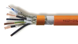
Braided shielding wraps around each conductor run to cover 85 to 100% of each bundle and mitigate noise. The maximum surface area a braided shield can cover is 90%. In contrast, spiral shields cover to 98%.
Usually, shielding is made of bare or tinned copper, though metal-coated Mylar is an option that lasts longest in servo applications that flex cable millions of times. Servocables with multiple signal and power conductors incorporate triple shielding: Around individual conductors, around twisted pairs, and around the entire cable bundle.
Shielding is woven around conductor strands at an angle compatible with the cable’s bending radius. For example, conductors can herniate out of wide braids, and smaller braiding angles withstand vigorous flexing. That said, shielding woven at larger angles is easier to attach and properly ground through end connectors. Ultimately the braiding angle is a compromise to satisfy both flexing and connection requirements.
Another shield feature is thickness. The drive’s high-frequency output generates high-capacitance leakage currents that flow over the shield and motor housing to ground. These currents determine the cross section of braided shields and shield connections because the shields mustn’t overheat from current flowing through them. (Shields that are too thin fail.)
3. Insulation.
Reducing cable capacitance reduces voltage overshoot, because there’s less capacity for the cable to build potential between drive pulses. So it’s helpful to decrease cable capacitance, which can be done by decreasing conductor diameter, increasing insulation thickness, and decreasing the insulation’s dielectric constant. The first two specifications are set by design requirements. Therefore, to further protect paired feedback conductors from the noise of power conductors and other feedback pairs, several servocable designs include low-dielectric polypropylene insulation. Common PVC insulation has a dielectric constant of five or more (though it’s normally not rated because fillers make inconsistent dielectric). Polyethylene insulation has a dielectric constant of 2. Polypropylene insulation has a constant of about 1.5 — approaching 1.0 constant of air.
4. Solid terminations.
Even connectors must include additional connections for shielding to attenuate noise.
Reactive noise-induced currents don’t help motors generate torque. They flow to ground as current leakage via cable shields and metallic motor parts. They can also flow through the motor shaft’s ball bearings and damage races with microwelds. In traditional designs, standard eight-pin connectors without shielding link cables, including those designed to common standards.
In contrast, some servocables connect to shields’ terminals through large, round connectors that ground copper braiding through a 360° metal contact.
Engineers should properly ground currents induced by noise by using electromagnetically compatible (EMC) cable glands to secure the cable to equipment while attaching the cable’s ground wire to the panel-bus ground terminal.
Servocables to transmit sufficient power
Conductors carrying power in hybrid servocables must be large enough to withstand an application’s load current, which is current drawn by the motor during normal operation. Only conductors of sufficient diameter (and sufficiently low gauge number) can supply this current and withstand, power-supply variability, overvoltages, inrush currents, and overloads when current draw exceeds the system’s rated limit.
When conductors are too small, cables typically overheat and fail. Normal operation heats cables because wires carrying current always have some resistance. Overloading, however, causes multiple hot spots that age localized areas of the conductors’ insulation. Several small faults degrade performance until the cable leaks too much current to be usable. Conversely, overly large conductors unnecessarily raise cable capacitance.
Another rule of thumb for continuously flexing applications is that cables shouldn’t exceed 325 ft. (Stationary applications tolerate longer runs.) Cables that are as short as possible reduce cost and transmit at a more stable voltage than longer runs. However, in long cables especially, high capacitance can cause reactive currents that tax the drive. Then, because of the drive’s overcurrent limit, sometimes it’s impossible to feed the motor enough power.
In addition, typical servodrive voltage frequency is 0 to 400 Hz (depending on motor speed) that creates up to 100‑MHz harmonics. Cables in these setups transmit the frequency and harmonics to the motor. When the power conductor’s impedance differs from those of the drive’s connections and motor’s windings, impulses bounce between the cable’s ends (called reflective wave phenomenon). If the cable is longer than the harmonic’s wavelength, the impulses generate electrical surges. If the cable is shorter, transient responses generate voltages a few times greater than motor voltage. Peaks repeatedly load the cable insulation, so insulation must be sized to prevent voltage peaks from causing the cable to fail due to arcing between conductors and shield.
One caveat: Cables with polypropylene insulation reduce cable-related losses with low capacitance, so can be longer between drive and motor than comparable cables with PVC insulation.
Environment and movement
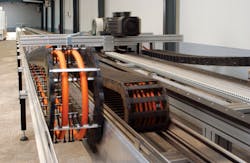
Like any cable, hybrid servocables must withstand the application’s movements, including their length, speed, acceleration, and bending radius. Static applications are more forgiving unless the installation space requires that cables bend or twist around obstructions. Dynamic applications involve constant flexing and usually need specialty conductor stranding, insulation, and jacket materials, plus tracks to keep cables untangled.
The cable’s operating environment also dictates what jacketing compounds are best. Cables must withstand exposure to oils, coolants, and chemicals. Outdoor cables must also withstand UV exposure, so they must have UV-resistant jacketing.
The last consideration is an application’s temperature. High temperatures slow currents, which necessitates larger cables. Cold temperatures also stiffen certain types of insulation and jacket materials. Only engineered PVCs, polyurethanes (PURs), silicones, and polyolefins withstand cold without becoming rigid or cracking.
Meeting regulatory approvals
Engineering regulations dictate what features hybrid servocables should incorporate. For machines sold in the U. S., cables need UL approval. For machines sold or used outside the U. S., regulations from CSA, CE, IEC, VDE, CCC, and GOST-R may apply. Within the U. S. and Canada, UL/CSA approvals and certifications dictate cable materials, ampacity (electrical current a conductor carries without failing), temperature range, flexibility, jacket thickness, shielding, and flame resistance.
For example, in some installations, cable insulation and jacketing must be flame retardant or self-extinguishing, or outgas minimal harmful gas (in low-smoke zero-halogen or LSZH versions) in case of a fire. But manufacturers generally don’t design and construct cables to get approvals or certifications. More often than not, cables earn UL/CSA approvals after they’re built for an application. Then engineers determine which UL/CSA codes they meet.
Using hybrid servocables with an array of approvals is sometimes simplest, as it lets OEMs specify a cable for many jobs, thereby reducing inventory. All-in-one servocables today generally meet UL AWM 2570, 21233, or CSA AWM I/II A/B. They come in versions to fit all servomotors, though Lenze, Siemens, Bosch Rexroth, and other servodrive and motor manufacturers have developed standards for other manufacturers.
In fact, because every servomotor OEM specifies ancillary products like cable and connectors to meet motor requirements, related standards sometimes take on a life of their own. For example, the cabling conventions of electric drive and control manufacturer Indramat (now of Bosch Rexroth) were so widely used that they’re still an industry standard. Indramat-style servocables have a conductor pair to accommodate signals for brakes and a pair for signals from temperature sensors, just as other hybrid servocable designs. However, old versions of Indramat cable don’t meet the same shielding or resistance requirements, so legacy cables can have crosstalk and noise issues and shouldn’t be used in new single-cable servomotor applications.
Today, manufacturers’ standards differ in three ways:
• How they size the cross-sectional area of the power conductors and signal pairs they define.
• The number of additional feedback-carrying pairs they demand (whether it’s none, one, or two).
• How they color-code conductor strands. For example, Lenze has a brown-and-white color code for the brake pair, while Siemens’ brake cable is black and white. Bosch Rexroth’s brake cables are black with white numbers. Cable manufacturers worked with encoder OEMs, as well as servodrive manufacturers, to devise unified cable designs.
How hybrid servocables help
Hybrid servocables connect drives to motors and offer distinct benefits. Specialty jackets and insulation isolate multiple conductor runs, so a given servocable is far thinner than the sum of separate cables for the same application and only slightly larger than a single power cable.
For drive-system manufacturers, they reduce drive construction cost (with fewer connection ports), reduce motor construction cost (by eliminating the feedback connector), and increase reliability (by eliminating separate encoder interfaces).
For OEM machine builders, they reduce overall drive system cost because of fewer cables and less time installing in machine, reduce number of cables and connections for better drive-system reliability, and minimize start-up troubleshooting.
For machine end users, they reduce machine costs, reduce number of cables and connectors to improve machine reliability, and minimize troubleshooting and maintenance.
At all manufacturing levels, servocables also reduce spare-parts inventories.
Summary: Specifying servocables in five steps
1. Determine the voltage and full load current of the servomotor to estimate the size of power conductors.
2. Determine how many conductor pairs needed for encoder, brake, and temperature feedback.
3. Calculate what conductor size provides adequate current to the encoder for the length of the drive cable.
4. Establish whether the application is stationary or dynamic. If it’s dynamic, work with manufacturers to calculate the minimum bend radius, required cycle life, and whether a drag chain or torsional flex cable is needed.
5. Consider the application’s environment and whether it necessitates chemical resistant, outdoor compatible, or abrasion–resistant cable.
6. Establish whether UL, CSA, CE, IEC, VDE, CCC, or GOST-R, or even multiple approvals are needed.
Final note: Variable-frequency drives (VFDs) and servocable differences
In some cases machine builders can use VFD cables to power and send control signals to servomotors. That’s because what’s billed as VFD cable is a lot like servocable, and for good reason. Many servo-driven designs share characteristics with VFD-driven designs, so VFD cable addresses the same challenges related to noise and crosstalk as servocable.
The main difference is that VFD cable typically only has one or two signal conductor pairs. In addition, cables designed for VFDs usually have shielding including both a braid to redirect low frequencies and a foil to redirect high frequencies. Flexing servocable can cold work and crack this foil. Therefore, servomotor applications that can’t use VFD cable flex the cable too much or need more than four conductors, as in applications that need data transmission from brake controls and temperature sensors. For the latter, a pair of signal conductors for the brake sends signals to the controller to hold the motor in place when the motor needs to stop. Another pair of feedback conductors for temperature sends signals from sensors to switches to turn off the motor before it overheats.
Edited by Elisabeth Eitel.
About the Author
Voice Your Opinion!
To join the conversation, and become an exclusive member of Machine Design, create an account today!

Leaders relevant to this article: