
For sheet metals and plates, resistance spot welding remains a widespread choice for joining similar metals. It is inexpensive and the resulting joints are strong and reliable. That’s why resistance welding is so widespread in automobile manufacturing. But to get the most out of the design and welding, the product should be designed for welding. Here are some DFM features that make resistance spot welding more effective and efficient.
Part thickness. Ideally, parts or plates of equal thickness will result in evenly spread weld nugget (the molten metal that quickly cools and solidifies into a round joint). But most of the time, plate thickness varies, and in such cases spot weld is effective only when the ratio of plate thicknesses is 3:1 or less. Using a filler electrode will produce effective weld nuggets and give the joint adequate strength. And, the plate surface should be flat or coplanar to simplify the welding process.
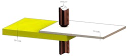
The proper ratio of plate thicknesses should be 3:1 or less. In this case, the upper plate is 2-mm thick and the lower one is 6-mm thick. So, the ratio is 3:1 and within the limit.
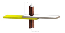
Brackets and stiffeners. Spot welding thermally deforms the pieces being joined with deformation greatest on the thinner piece. Thus, when stiffeners are used to provide added structural stability to the joint, selecting appropriate thickness is important. Stiffeners and brackets should be thinner than or equal to the thickness of the exposed surface of the base plate.
Weld proximity and edge clearance. To get the best weld quality and strongest joint, the distance between consecutive welds (aka pitch) and between individual welds and the edge of the part (clearance) must meet specific criteria. The pitch should be 10 times the material thickness for the best strength and to avoid any adverse effect on the part. Theoretically, a pitch of 20 times the material thickness reduces the shunting effect (where current travels from the weld being made to a nearby already-made nugget and not enough heat is generated in the joint being formed, making it weaker and unreliable).
It is also good practice to maintain twice the spot-weld diameter from the center of the weld to edge of the workpiece. This rule also applies to slots and holes midway between the plate surfaces. If this minimum distance is not maintained, the electrode may not apply enough pressure and cracks may develop, leaving a porous weld. Sometimes, it may also lead to excessive burrs or deformation of metal.
D = 2d, d = spot weld diameter.
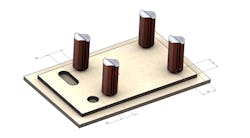
Distance between weld and slot or holes.
Distance between weld and form. When sheet-metal parts having any kind of form, bend, or draw are to be welded, there should be a minimum distance of a spot-weld diameter (D) plus one bend radius (D + R) between the electrode and form to prevent shunting. Designers should ensure this bare minimum clearance to avoid fabrication errors.
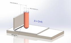
Weld space: distance of form to the center of the spot weld.
Spot weld overlap region. Spot welding is only done on pieces that are coplanar, so the overlap region of both workpieces has a significant impact on weld quality. It is necessary to have appropriate overlapping lengths of the sheets to attain better dimensional accuracy and join the sheets without large deformation. Usually, the overlap length depends upon the material being welded and its thickness, but is not usually more than 8 mm in diameter.
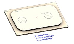
Overlap region for spot weld.
Projection Welding
Projection welding, a small refinement of resistance spot welding, uses earlier projections to reduce the consumption of power to make a resistance weld. It also reduces shunting effect—a major limitation of spot welding—allowing for closer weld-to-weld spaces and making it possible to weld the jobs that have smaller flanges.
Usually, projection welding is used for materials such as low-carbon steels and alloys, as well as aluminum having a thickness around 3.18 mm. But workpieces below 0.25 mm thickness would need spot welding only, as the higher temperatures of projection welding would result in the workpiece collapsing. Projection welding is less expensive than spot welding, but requires precise positioning of workpieces and electrodes, in addition to precise tolerances.
These design rules ensure that parts are designed with the intent to reduce design revisions and reworks, which will take care of 70 to 80% of the costs. The remaining costs are for manufacturing, which can be minimized by specifying correct processes and methods in the drawings.
Axial, shear, and bending strength of welds vary as a function of strain generated in the component, and they depend on the pressure generated through the electric current during the welding and the distance of the electrodes from the workpiece. Thus, designers should specify tool clearances in drawings along with standard weld symbols, based on the intended design characteristics.
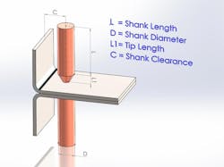
Spot weld and tool clearance >= 3 mm to avoid interference of the weld gun.
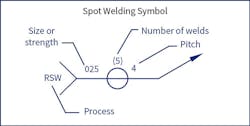
Spot weld symbol.
Following a good design rulebook should reduce rework and waste due to bad welds, but it doesn’t guarantee that the designs will not fail or component will withstand extreme cases. Designs adhering to DFM must still undergo design analysis to ensure the reliability and appropriate functioning in operational conditions. The conventional approach of designing with DFM rule books and then calculating the strength of critical components for optimization will show a dramatic reduction in the overall costs of manufacturing a product.
If you have any questions regarding DFM for spot welding designs & drawings, please feel free to contact an engineer at Hi-Tech CADD Services.

About the Author
Usha B. Trivedi
Engineer
Voice Your Opinion!
To join the conversation, and become an exclusive member of Machine Design, create an account today!

Leaders relevant to this article: