Specifying the Right Hydraulic Cylinder for the Right Job
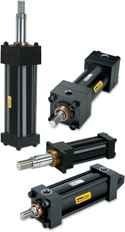
Hydraulic cylinders essentially convert fluid pressure and flow into force and linear motion. They are available in a wide range of styles, sizes, materials, and configurations. Many OEM engineers play it safe by over-engineering cylinder specifications. But less can sometimes be more when it comes to complex hydraulics. Let’s first identify some of the key factors that should be considered when specifying hydraulic cylinders.
Design Factors for Hydraulic Cylinders
Specifying hydraulic cylinders is essentially a balancing act or a cascade of compromises, as each design factor influences one or more of the other design factors. Designers must weigh each positive effect against potential negatives to get the best performance. Here ‘s a concise look at those factors:
Capacity. Most industrial hydraulics are considered medium-duty and operate at 1,000 psi. Heavy-duty hydraulics, which are common in presses and automotive machinery applications, can handle pressures up to 3,000 psi. If loads are extremely high, tandem cylinders are preferred to larger-bore or custom high-pressure cylinder designs.
Stroking distance. Stroke distances can exceed 10 ft (5.05 m) for custom-built cylinders, but pressure ratings can be a problem with such long strokes. The rod diameter needs to be determined in order to gauge its ability to handle the load. If necessary, a pressure rating on load in thrust (push mode) must be specified. In horizontal applications, which are common, premature rod bearing wear can lead to rod sag over long strokes. Although custom stroke distances above 10 ft (3.05 m) are possible, pressure rating can be a concern.
Speed. Every application engineer has their own definition of “excessive speed.” A good rule of thumb is that standard hydraulic cylinder seals can easily handle speeds up to 3.28 ft/sec. (1 m/sec.). The tolerance threshold for standard cushions is roughly two-thirds of that speed. Standard low-friction seals are often a better choice for high-speed applications, but what you gain in one aspect of performance you lose in another. The higher the fluid velocity, the higher the fluid temperature. So, when opting higher speeds, it is essential to consider how higher temperatures will affect the entire hydraulic system. In some hydraulic systems, over-sizing the ports may eliminate concerns over higher temperatures.
Temperature. As previously noted, hydraulic cylinders using standard components can be designed to meet application temperatures as high as 500°F (260°C) and as cold as −65°F (−54°C). But temperatures affect both the “hard” and “soft” design components of cylinders. That means engineers designing applications that will see high and/or low temperature extremes must be aware of individual components interdependency to best balance short- and long-term performance. For example, seals and metal parts used in cold environments will contract.
Mounting styles. There are basically three mounting styles. Load, speed, and cylinder motion are the parameters that help determine which is best. For example, fixed and pivot mountings absorb forces on the cylinder’s centerline, the preferred way for mountings to handle the thrust or tension. These two types of mountings can usually be medium- or heavy-duty. A third style, fixed, supports the entire cylinder on its mounting surface below the cylinder’s centerline rather than absorbing forces only along the centerline.
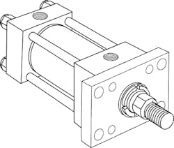
Style J (NFPA MF1)
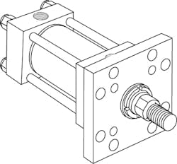
Style JB (NFPA MF5)
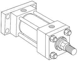
Style H (NFPA MF2)
For mounting cylinders, the best practice is to use a mounting style that absorbs forces on the cylinder’s centerline. If the piston is rod is primarily loaded in tension (pull), use head end mountings such as Style J and JB. If, however, the piston is primarily loaded in compression (push) use end cap mountings such as Style H.
Several standardized mounts within these styles give engineers alternatives for meeting application requirements. NFPA tie-rod cylinders, for example, are used in most industrial hydraulics and are typically mounted using trunnion-style heads and ; extended tie rod caps and/or head end styles; flange-style heads; side-lug and side-tapped styles; spherical bearings; and cap-fixed clevis designs. Most mounting options are available for single-acting and double-rod cylinders.
The purpose of the mount is to absorb forces, stabilize the cylinder, and improve performance. For rods loaded primarily in compression (push), cap-end mounts are recommended. For those in tension (pull), head-end mounts are preferred. The amount of tension or compression determines piston rod diameter. The amount of pull or push determines the bore diameter.
Every mounting type comes with its own benefits and limitations. For example, trunnions for pivot-mounted cylinders won’t work with self-aligning bearings where the small bearing area is at a distance from the trunnions and cylinder heads. Self-aligning bearings would introduce bending forces that could overstress the trunnion pins.
Many applications might seem like they need atypical mounts, but most can be handled by existing styles with only slight modifications, which simplifies replacement and reduces costs.
Standard NFPA Tie Rod Cylinders are used on machines critical in all phases of metal production, from smelters, casters, and extruders through grinders, rolling mills, and strip processing. Each cylinder can be customized to the application’s needs.
Other relevant factors to consider when selecting a mounting style include:
Cylinder bore size. Bore size is a function of operating pressure. The amount of push or pull (force) needed determines the bore size. In the past, steel and aluminum mill equipment often used non-standard bore and rod sizes. Today, virtually every industrial requirement can be met with NFPA standard and/or ISO-compliant components.
Piston rod size. Engineers probably request custom piston-rod sizes more than any other customized hydraulic-cylinder component. What they ignore is that push or pull are never independent of stroke length. Rods under compression or tension tend to diffuse force in non-linear directions. Specifying costly materials such as stainless or alloy steels for rods is another common example of over-engineering. But in extreme applications, chrome plating might be needed for corrosion resistance.
Cylinder configurations. For applications requiring equal force (pressure) on both sides of the piston, the preferred configuration is a standard double-acting cylinder using pressure to extend and retract the cylinder, combined with a four-way directional valve directing pressure to the head or end cap. It is almost always better than a customized set-up.
Experienced hydraulic manufacturers are familiar with practically every cylinder configuration—and the unintended consequences of customizing components vs. creatively combining standard cylinders to meet unusual performance requirements.
Rod ends/rod threading. This is one area where the standard options are so all-encompassing that customization is rarely needed. Additionally, standard threads can be made in inch or metric formats. Typically, each diameter is available in four distinct rod end styles. Even in rare instances where modifications seem to be called for, it is important to consider the effects of modifications on accessories. The relatively small performance increase from using standardizing rod ends is almost always warranted by the versatility standardization brings.
Even modest modifications, such as under-sizing threads, may require de-rating the cylinder and necessitate special tooling for a non-standard pitch. These actions cause delays, add expenses, and leave the cylinder unable to easily mate with accessories.
Cylinder body tube. Standard cylinder bodies are plain or chromed-plated and will handle most applications. Alloy steels, stainless steel, and brass are common in special applications such as wet environments.
Stop tubing. Stop tubing increases the distance between the rod and piston bearings to reduce bearing load on push-stroke cylinders when the cylinder is fully extended. Stop tubing is critical for horizontally-mounted cylinders as it limits the rod’s extended position. In such applications, increased distance yields greater stability and longer bearing life.
Seals. Experienced hydraulics manufacturers offer seals compatible with a range of temperatures and fluids and can help choose seal materials that meet application requirements.
There are applications that require cylinders customized in size, material, or configuration. However, partnering with an experienced hydraulics manufacturer early in the design phase saves engineering teams time and money while ensuring the final system does its assigned duties as efficiently as possible—for as long as possible.
Engineers specify hydraulic cylinders for handling many types of equipment, including machine tools, CNC turning, metal stamping, and assemblers.
Hydraulic vs. Pneumatic
Although pneumatic systems are in some respects simpler, they generally cannot handle the high loads and forces that hydraulic cylinders can. Hydraulic cylinders also have smoother, more controllable movement as they do not have the spring-like action associated with the release of pressurized air. As an added benefit, hydraulics can perform ancillary functions such as lubricating and cooling.
However, since the availability of power and media is a non-negotiable factor in fluid power system design, it should be noted that a properly designed and sized pneumatic system can achieve higher performance where a compact footprint is not required. Further considerations of pneumatic cylinder design are outside the scope of this article.
Although NFPA standards and ISO-compliant guidelines are a great starting point for hydraulic system design, many industries have guidelines of their own.
Jim Hauser Sr is senior engineer and division sales manager and Rade Knezevic is global account manager at Parker Hannifin Corp.
