Learn How Microstepping Can Provide Smoother Motor Motion

Microstepping is a major advancement in step motor technology introduced many years ago that allows motors to make finer steps in movement. By manipulating the current vector, microstepping creates very fine step resolutions. A smaller step size results in more precise positioning. It also reduces torque ripple, providing smoother motion and less vibration and audible noise. Many applications benefit from microstepping such as 3D printers that gain the capability to produce finer features and smoother surfaces as well as quieter in-room medical devices.
At one time, full stepping was the only affordable way to drive a step motor. The earliest step motor drives were full-stepping operations utilizing simple logic that resulted in less expensive drive electronics. Full stepping also made it possible to use the simplest drive: the L-R drive. This drive used switches and winding resistance (or an external power resistor) to control phase currents. The L-R drive only provided two values of current (plus and minus) in each winding and delivered very low shaft power.
The operation of L-R drives worked well for applications such as indexing a platen roller in a printer and other low-speed applications. However, the torque in an L-R drive system falls precipitously with velocity starting at rest, making it undesirable for most modern automation applications. Without robust high-speed torque, L-R drives are inefficient and limited to use in low speed and low power applications.
Figure 1 shows the torque versus displacement curves of a step motor driven in full step. Full stepping the motor only allows a full current application to motor windings, so the resulting torque curves are fixed 90 deg. apart. This causes a large variation of torque as the motor shaft turns, also known as torque ripple. Torque ripple creates rough motion and audible noise. The equations governing the torque for each phase are:
TA = K T sin (θ)
TB = K T sin (θ − 90◦)
T-A = K T sin (θ − 180◦)
T-B = K T sin (θ − 270◦)
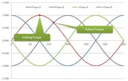
1. Holding torque is the amount of available torque to hold the motor shaft in the desired position. If an external force exceeds the holding torque, the motor shaft will jump to another position, typically 7.2 deg. away from the intended position. Pullout torque is the amount of available torque to accelerate an inertial load or to overcome friction while the motor is moving.
Advantages of Microstepping
Modern step motor drives use switch-mode PWM power amplifiers to control winding currents as well as much more complex logic (embedded processors) that allow for microstepping. Advances in processing and sensing make it possible to divide the typical hybrid step motor’s 1.8 deg. full steps into much smaller steps (Fig. 2). In dividing each full step into 10 microsteps, this formula would determine the first microstep past Phase A:
T = 0.988 * sin (θ) = 0.156 * sin (θ − 90◦)
T = 0.988 * Phase A + 0.156 * Phase B
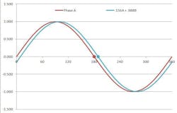
2. This chart illustrates how microstep torque vectors are much more closely spaced than full step vectors. This can be utilized to achieve smoother motion and precise positioning.
The magic of microstepping is more precise control of the current in each winding and, thereby, more precisely controlled torque and position. Applications benefit from less vibration and noise. Almost any modern hybrid step motor can benefit from microstepping as their designs allow for optimizing the magnetic elements for sinusoidal torque versus angle.
Microstep Emulation Simulates Microstepping for Low Frequency Indexing Systems
Many indexing schemes (such as low-frequency output on a PLC) cannot provide high-frequency step signals. In these cases, microstepping would drastically reduce motor top speed. In addition, many machines are designed around coarse resolution indexers (limited to full- or half-step resolution), making it impractical to change to a microstepping regimen.
Microstep Emulation supports synthetic microstepping in achieving slow-speed smoothness and high-speed operation. The process accepts coarse resolution step signals from the indexer and synthesizes the commanded motion using the drive’s own internal high-resolution microsteps. This high-speed process “locks” onto the incoming step sequence and follows it in smooth microsteps. Smoothness of motion can be nearly as good as true microstepping. However, the final position will be not be as precise as microstepping as it consists of multiple of full steps (Fig. 3).
Machine builders should consider microstep emulation if the controller is limited in speed to full steps. If the controller can provide the high-speed pulse rates necessary for microstepping, then the drive should be set for microstepping.
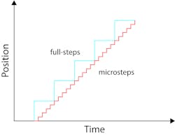
3. The driver electronically divides each incoming full step into several microsteps. The total distance moved is the same, but torque ripple is reduced by employing torque vectors that are more closely spaced.
Performance advantages of microstepping over full-stepping are numerous, including more precise position and torque control, less vibration, and less-audible noise. While these advantages benefit all step motor applications, they are particularly beneficial in precision applications such as 3D printing, image scanning, camera or sensor positioning, precision assembly, and much more.
Applications with controllers that don’t provide high-frequency pulse signals can still employ the benefits of microstepping by using drives that offer microstep emulation. High-speed applications might work suitably with full stepping motors. However, the risk is lower and performance better when employing microstepping or Microstep Emulation. Your motor/driver source should offer the resources to simplify the process.
Available to engineers are online calculators that help determine what the microstep emulation should be. There are two ways drives can enable the Microstep Emulation feature in its motors:
- Stepper drives and integrated steppers are set with on-board dip switches. Operators select the 200 SMOOTH (full-stepping with Microstep Emulation) or 400 SMOOTH (half-stepping with Microstep Emulation) dip switch settings.
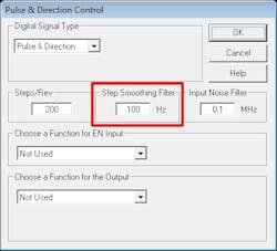
- Using ST Configurator software, operators can adjust the Step Smoothing Filter value in the Motion > Pulse & Direction Control dialog (screenshot). The lower the Step Smoothing Filter value, the greater the impact of Microstep Emulation. A lower value results in more synthetic microsteps injected into the command motion. For example, a Step Smoothing Filter value of 10 Hz will generate extremely smooth motion, while a value of 1,000 Hz or higher is equivalent to running the motor with the original, low-frequency step resolution.
Jeff Kordik is the chief technology officer and Eric Rice is a marketing director at Applied Motion Products. For more information on microstepping, please visit Applied Motion.

About the Author
Jeff Kordik
Chief Technology Officer
Eric Rice
Marketing Director
Voice Your Opinion!
To join the conversation, and become an exclusive member of Machine Design, create an account today!

Leaders relevant to this article: