Five Tips for Improving Plastic Injection Molding Design
The global market for plastic injection molded parts is currently valued at $325 billion, and this number is expected to grow by 5.7% through at least 2025. Spurred by the rapidly developing economies of Asia, and taking advantage of process efficiencies as well as new resin chemistry, the use of plastic components in ever more sophisticated applications poses enormous opportunities—and challenges—for product designers and industrial engineers.
One of the notable advantages to plastic injection molding, of course, is the ability to produce very high volumes with a low unit price relative to development costs (tooling). However, these same high volumes demand the use of good design practices. Even small, incremental improvements to tool design, which might be insignificant in small batch production, can have a major financial effect when considering millions of finished parts. That’s why it makes good sense to apply sound design logic at the outset of any tooling project.
While designing two multi-cavity molds for a product that will be used in a high-temperature environment, I found four key considerations that universally apply to any project for any application. The following is my experience designing the mold for this part.
Design for the Material
Every thermoforming resin has unique chemical and mechanical properties that need to be mated to the tool steel that’s going to be used to mold it. For example, when using PEEK, a high-temperature engineering plastic used in automotive, aerospace, and medical applications, the tool needs to withstand higher molding temperatures while maintaining dimensional stability.
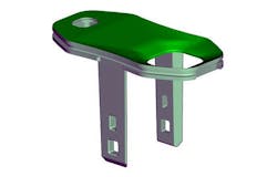
1. Part made from high-temperature PEEK plastic.
For this tool, my choice was to use S136 stainless steel. Stainless steel works well for large production runs at the higher temperatures PEEK requires. Stainless steel resists the abrasion of glass fiber, and takes a high polish for a superior surface quality finish.
As mentioned, PEEK must be injected at high pressures and temperatures, and therefore the tool must be carefully heat-treated. The treatment of course is done before final polishing and after CNC machining.
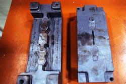
2. Rough milled inserts before polishing and heat treatment.
Since S136 stainless is not an inexpensive tool steel, it’s recommended to machine only a partial mold tool insert to reduce the total tooling costs. Once prepared, the insert can be put into a larger modular die of a more standard tool material like P20 or NAK80, and then this is turn gets mounted into the machine.
To maintain the necessary high molding temperatures, which for PEEK typically exceed the standard heating circuits of most injection molding machines, a separate electrical heating coil must be used. Electrical heaters can distribute heat very efficiently and uniformly for good molding results, but that in turn places a premium on proper design of the cooling channels to remove this heat quickly for good cycling times.
Design for Draft Angles
Resins have unique shrink rates and percentages which can cause the molded part to stick inside the cavity. The manufacturer’s spec sheet can help determine minimum draft angles, but this is also affected by the part’s surface texture. To a certain point, more texture requires more draft.
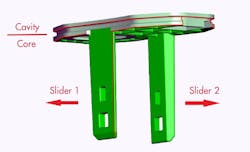
3. Moving the parting line requires a draft angle.
It’s very common for product designers to specify parting lines at the right-angle intersection of two perpendicular faces. If one of those faces is a cosmetic surface, it may be damaged if there is any flash in the mold.
To avoid the possibility of this damage it’s a good idea to move the parting line away to the adjacent, non-cosmetic face. That parting line should be moved along a draft angle of a few degrees, not 90 deg. If flash should occur it can then be trimmed off without damaging the look of the finished part.
Design for Wall Thickness
Managing wall thickness is important for controlling stress marks and to ensure the design is meeting minimal wall thickness while maintaining as much consistency as possible in the thicknesses of adjacent features.
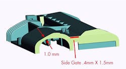
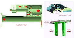
4. High injection pressure is applied near the gate.
The gate represents an area of high initial injection pressure. A narrow wall thickness also implies a restriction which increases injection pressure. These two forces, if not balanced out, can create shear, flashing, and even damage to the mold. Therefore, it’s good design practice to increase wall thickness near the gate, decrease injection pressure, or both.
Second, there is an increased likelihood of flash because the pressure is exerted precisely on the split line. If a flash occurs, it will take significant time and effort to remove, leaving a corresponding mark on the finished product. Lastly, adjacent areas of unequal mass will cause sink marks. These are not only unsightly but can also compromise the part’s structural integrity.
Design for Ejection
The application of ejection force should be balanced out over the surface area of the part—taking into account thickness and mass—to keep the part from warping or breaking. Additionally, in the area surrounding the gate, stripper plates or additional ejector pins will be needed. These pins are necessary to clear the gate of plastic in the event of a short shot.
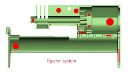
5. Geometries are challenging to balance.
Since the area near the gate will be under stress, it’s good practice to make the wall thicker if possible or create pads or other flat areas to provide a push-off for the force of the pin to act against.
While there are many things to consider when trying to improve your plastic injection molded design, if you can take these four tips into consideration, you’re on your way to making a high-quality product. As designers and product engineers continue along the new product development journey, it’s crucial to have a keen understanding of the nuances of plastic injection molds and how to mitigate them.
Gordon Styles is president and CEO of Star Rapid.

About the Author
Gordon Styles
President and CEO
Voice Your Opinion!
To join the conversation, and become an exclusive member of Machine Design, create an account today!

Leaders relevant to this article: