The Fine Art of Selecting Drive and Guidance Technology for Linear Units
Integrating a linear drive and guide into a single, sealed unit can provide a high-performing, robust and compact motion solution with a long, predictable lifespan. There are, however, many drive, guidance and sealing configurations from which to choose, and each one has special features favoring precision, load handling, durability, maintainability, environmental resistance or other application requirements.
This doesn’t mean that the high-precision component you specify for one application will always be right for the next one with a similar profile. Aside from the motion parameters mentioned above, business priorities, installation restrictions and many other requirements may interfere. Understanding the strengths and limitations of linear guidance components is a good place to start down the path to the optimal system.
Linear Unit Overview
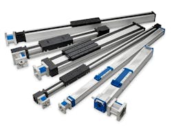
Each linear guide configuration includes a drive mechanism that translates the rotating motion from a motor into the linear thrust that moves the load attached to a carriage. Linear units also support the drive with a guidance structure and protect the mechanism within a sealed cover (Figure 1).
Drive Components
Drive technology for linear units is often based on ball screw or belt technology, which differs in how they transfer rotary motion to linear motion as well as mounting.
Ball Screw Drives
Ball screw drives typically translate motion through a recirculating system of ball bearings, which are the intermediary between the shaft and the nut. They ride between helical threads of the shaft and a correspondingly threaded nut that carries the load. When the motor rotates the screw, it engages the balls within the corresponding threads, providing the leverage that drives the nut back and forth along the shaft, carrying the load with it.
The rolling balls offer minimal resistance to motion and thus less friction. This transmits force more efficiently with less energy loss and physical wear. Ball screw drives provide a durable, heavy-duty solution, combining high precision, load handling, stiffness and repeatability with minimal maintenance (Figure 2). They can use a low-cost lead screw with a preloaded nut, a standard commercial rolled ball or a high-precision ground ball screw.
READ MORE: Eight Red Flags to Avoid for Longer Ball Screw Life
The chief drawbacks of ball screws are that they are more costly than belt drives, and their performance and durability degrade at high speeds.
Belt Drives
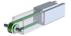
Belt drives translate motion using a belt looped around a rotating drive pulley connected to the motor shaft and an external pulley located away from the motor. When the motor rotates, the belt moves in the direction of the rotation while tensioning mechanisms sustain contact with both pulleys. This carries the load much like the rolling pulleys of a conveyor belt move its contents in a linear path.
The belt can use a toothed gripping mechanism (Figure 3) or a wide variety of plastic, rubber, leather or other materials capable of gripping and driving the load.
Belt drives offer design flexibility by enabling longer strokes, greater control over speed and direction, and the ability to absorb shock and vibration. Belt drives can also be cost-effective for high-throughput and high-speed transport because their sliding surface traction does not degrade significantly at high speeds. Belt drives are especially adept at accommodating dynamic changes in speed and direction.
Slippage is one drawback of belt drive technology. Heat, dust, chemical exposure and other wear can loosen the belt, reducing efficiency and increasing failure risk. To address this, vendors might provide idler pulleys or adjustable tensioners that maintain proper tension in the belt automatically, preventing slippage and reducing the frequency of belt replacement.
Guidance Component Characteristics
Regardless of whether it is a screw or belt architecture, achieving optimal performance requires a support structure, which typically comes in the form of slide guides, rolling balls or wheels.
Slide Guides
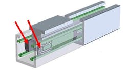
Slide guides, also known as prism guides, are self-aligning guidance structures in which a plain polymer bushing slides on an anodized extrusion surface to provide full, surface-to-surface contact at every point (Figure 4). This functionality enables cost-efficient, smooth, reliable and maintenance-free guidance, which is also highly resistant to shock loads, dust and dirt.
So much surface-to-surface contact, however, increases resistance and demands more force to move the load, resulting in more friction, greater wear and a shorter life. Utilizing self-lubricating polymer bushings made of advanced polymers such as Robalon, however, reduces friction considerably, increasing the load capacity and reducing wear. Self-lubricating bushings can, in fact, increase durability as much as tenfold versus no self-lubricating bushings, while also virtually eliminating the need for maintenance.
The sliding surface architecture is also relatively quiet, stable and more tolerant of shock loads. Since the sliding surface is part of the unit body, there is no need to incur the added costs of designing in an external rail. A 2-meter slide guide, for example, would cost about the same as a 10-meter guide.
Ball Guides
Ball guides, much like ball screw drives, use balls that roll between the nut and the screw shaft. The relatively small contact area of the balls offers less resistance and thus produces less friction.
Also like ball screws, ball guides contain the balls in a recirculating channel, further minimizing friction and extending service life. This low-friction design enhances precision and load handling, helps withstand high payloads, and moment loads and contributes to high stiffness (Figure 5).
For applications requiring even higher payloads, motion system providers such as Thomson offer precision-machined screw and nut systems with deeper groove designs, allowing the nut to accommodate balls almost double the size of a standard guide. This increases the contact area dramatically, improving the load-handling capacity without increasing the overall size of the guide, which can be especially valuable in distributing load in constrained spaces.
READ MORE: Unleashing the Capabilities of the Linear Servo Press in Manufacturing
When using ball guides in high-precision applications, however, it is important to note that some of that precision comes at the cost of greater vulnerability to contaminants. Small particles that lodge under a single ball can compromise the circulation of the entire ball train.
Wheel Guides
Wheel guides are built for speed. They rely on rolling motion as well but use wheels on tracks instead of in ball cages (Figure 6). This architecture enables wider carriages, which helps counter moment loads. It also enables moving high loads with high acceleration, contributing to the ability to function efficiently amidst dynamic, constantly changing operations.
Depending on the application, wheel guides can be more durable than slide guides, even those using self-lubricating bearings. Their rolling technology makes them suitable for higher-speed operation comparable to or exceeding ball screws, while the simpler tracking assembly offers flexibility and cost efficiency compared to sliding surface guidance.
Environmental Resistance
Enclosing the motion components within a sealed cover band can be a first line of defense against ingress of foreign objects through the opening of the profile in which the carriage runs. The cover bands are usually plastic or stainless steel.
Corrosion-resistant plastic bands can seal the unit by snapping into grooves along the carriage opening, while stainless steel bands might utilize magnet strips for sealing. Units with self-adjusting tensioning mechanisms can eliminate slack and improve sealing integrity. A designer may combine materials—such as stainless steel for adapters and anodized aluminum for cover tubes—to effectively balance corrosion prevention, weight and cost.
Linear Unit Configuration in the Real World
Understanding the relative strengths and weaknesses of linear units can help guide you in choosing ideal pairings for linear drives and guidance solutions. All else being equal, for example, an application that calls for high payload, precision and stiffness might benefit from pairing a ball screw and ball guide. Likewise, that ball screw could pair with the slide guide to get higher thrust or greater durability. When designers want higher speed and smoother operation, belt/wheel pairings might come into play, while lower cost and challenging environments might bring belt/slide pairings into the discussion.
While there are many tried-and-true pairings of drive and guidance components, all applications are different, and there are usually multiple solutions. Here are just a few examples of ways in which a design engineer might start on one path and end up somewhere else.
- A designer needing a ball/slide pairing to fulfill a large order might anticipate a future product design change that would require more precision. To eliminate potentially higher design costs later, they might conclude that it would be more economical to absorb the cost of implementing the higher-precision component now.
- An application for a harsh environment subject to vibrations and temperature fluctuations might benefit from choosing a higher-precision pairing that would allow for a larger margin of error amidst the less predictable hazards.
- Designers commonly specify belt drives for faster, lightweight applications, but when outfitted with larger pulleys and paired with a ball screw drive, they might achieve higher speeds at lower costs than would otherwise be possible.
- Guides using sliding surfaces may generate too much particulate matter for robotic applications in cleanroom environments, so designers may switch to recirculating ball guides.
When you factor in the range of sizes and dimension options for each component, the material and maintenance considerations, the options are infinite. While the design engineer’s judgment can get close to the optimal solution, working with a vendor’s engineering team, along with simulation and automatic selection tools, would likely lead to the optimal solution faster.
Playing it Safe
Regardless of how well-designed a linear guidance solution is, its effectiveness ultimately depends on how users apply it—something largely beyond the designer’s control. Frequent overloading of a machine designed for extended operation can quickly lead to failure.
READ MORE: Design a Universal End-of-Arm Tool for Intralogistics Applications
To mitigate risk, linear unit manufacturers build in safety factors that create a buffer between maximum load or stress and the potential for exceeding those limits due to manufacturing variations, real-world operating conditions, material fatigue and load distribution variations. This design approach is something that all manufacturers do differently but do not always state clearly.
Higher-safety factors reduce the risk of issues from unanticipated overloading, but excessively high factors can compromise performance efficiency and increase size and weight. Selecting the appropriate safety factor requires a careful balance of performance, reliability, cost and system complexity. When interpreting vendor-provided safety factors, ensure that you understand how operating at those levels might impact speed and longevity.
It’s All in the Application Details
A well-optimized linear unit offers a versatile, compact motion solution that can reliably serve an application for years. Achieving this optimization requires a complex interplay of drive, guidance and protection choices. Expertise from an experienced linear unit designer, supported by automated design tools that process options and manage tradeoffs efficiently, is crucial.
The right solution will depend on the engineer’s judgment informed by an understanding of, and appreciation for, the unique capabilities of motion control components in the context of complementary parts and operating conditions.
This article was submitted by Hans Dahlen, senior product manager – Linear Units, Thomson Industries, Inc.


