Energy-Saving Electrical Pumps Satisfy New DoE Standards
This file type includes high-resolution graphics and schematics when applicable.
The mechanical world is becoming increasingly electrical. The evidence is everywhere, from consumer goods, public transportation, elevators, escalators, and vehicles to various pumps, drives, and valves used in industrial equipment. In many industrial environments, electrical actuators are rapidly replacing hydraulic or pneumatic power sources.
Generally, electric actuators use a single-phase or more common three-phase electric motor with a gearbox to create the torque required for operating the moving elements. The actuators may be pumping liquids, such as water, pharmaceuticals, chemicals, oil, or natural gas, or merely driving a mechanical system. Such electrical motors sometimes consume a large amount of the total energy consumed by a system when in standby mode. This much wasted energy adds up, substantially increasing both the operating and maintenance costs of electrically actuated devices.
Since 1997, there have been regulations in place that set minimum efficiency standards for general-purpose, three-phase motors rated as low 1 hp and as high as 200 hp. These regulations were updated in 2010, when the Energy Independence and Security Act of 2007 (EISA) went into effect. (See also “NEMA Application Guide for AC Adjustable Speed Drive Systems,” December 2007.)
This legislation raised the minimum efficiency levels of the motors covered by the earlier legislation. It also extended the regulations to electric motors up to 500 hp, as defined in the National Electrical Manufacturer’s Association (NEMA) Standard MG 1-2011.
The U.S. Department of Energy (DoE) recently released new efficiency standards for commercial and industrial pumps that are based on efficiency levels negotiated by manufacturers, efficiency advocates, and other stakeholders. In addition to establishing the first-ever national efficiency standards for pumps, the final rule also provides a mechanism for energy-efficiency programs to incentivize high-efficiency pump packages.
The new standards apply to clean water pumps between 1 and 200 hp, which are used for a wide variety of applications such as irrigation, circulation of hot and cold water in commercial buildings for heating and cooling, and pressure boosting in high-rise apartment buildings. The standards will require the least-efficient 25% of today’s pumps market to be redesigned to improve efficiency and reduce energy losses.
Pumps meeting the new standards sold over 30 years would reduce electricity consumption by about 30 billion kilowatt-hours, which is equivalent to the annual electricity use of 2.8 million US households, and save customers $0.4 to 1.1 billion. The standards reflect efficiency levels that were agreed to by manufacturers, efficiency advocates, pump users, and utilities as part of a negotiated rulemaking, and build on standards established in the European Union.
The new standards are based on a metric that incorporates not just the power consumption of the pump itself, but also of the motor that drives the pump and any controls. In many pump applications, the required flow is variable. Oftentimes, this variable flow is achieved by opening and closing valves, which wastes a significant amount of energy.
A better option for variable-load applications is to control the pump with a variable-speed drive, which adjusts the pump output to only meet the required load. Overall, it can help reduce energy consumption by up to 50% or more.
The energy-saving benefits of variable-speed drives are captured in the new metric, such that a pump with a variable-speed drive will have a significantly better rating than a constant-speed pump. The new ratings for pumps will arm customers with more information when making purchasing decisions, and provides a mechanism for utilities and other efficiency program administrators to incentivize high-efficiency pump packages.
The regulations cover all drives sold in the U.S. and motors installed in machinery imported for sale. Canada and Mexico have similar regulations.
In addition to these regulations, the DoE has what’s called the “Small Motor Rule.” This rule applies to general-purpose two-digit NEMA frame (and IEC equivalents), single- and three-phase, 1/4- through 3-hp motors in open enclosures. This regulation went into effect on April 9, 2015. NEMA has published a white paper to help manufacturers and users interpret this rule and meet the requirements.
The Measurement Challenge
To accurately determine the efficiency of today’s electrically driven systems, the measurement system being used must make both electrical voltage and current measurements, calculating electrical power. It must simultaneously measure torque and speed, calculating mechanical power or even flow and pressure, or calculating hydraulic power. Once the data-acquisition system makes the power calculation, the ratio determines power efficiency.
In addition to measuring power efficiency, you may also need to analyze power quality as part of your product design or system testing. Electrical actuators may cause voltage sags or excessive harmonic distortion.
These more accurate measurements can find problems in the design and testing phase, or in maintenance jobs. And because these data-acquisition systems also acquire sensor signals from torque, speed, displacement, flow, pressure, temperature, and humidity, it may be easier to determine the cause of a power-quality problem.
Another advantage of using a single data-acquisition system, in comparison to a collection of special-purpose instruments or handhelds, is that it saves time processing the test data. Many instruments are unable to stream and store raw signals. The raw data is helpful in analyzing the overall efficiency, load situations, and special conditions, or detect anomalies. Although some instruments have an option to interface with mechanical measurement devices, they can be expensive and lack seamless integration, thereby leaving the end user with a do-it-yourself task.
Case Study: Measuring the Efficiency of a Pump’s Three-Phase Motor
For most industrial applications, engineers use three-phase motors. One reason for this is that a three-phase motor is typically 50% more efficient than a comparable single-phase motor.
Another reason to use three-phase motors is their ability to self-start. Single-phase induction motors have no starting torque, so you must provide an auxiliary means of starting them. Single-phase motors also vibrate more than three-phase motors. This can lead to premature failure of the motor or machine that it is powering.
Isolating the data-acquisition system from these hazardous voltages and their transients is important. Most inputs of data-acquisition systems are not isolated and may not save enough for the user. In addition, they may not able to handle transient voltages. Before using a modern instrument, one must look into its specs and measurement category according to the IEC 61010 standard. The measurement category and the accordingly listed voltage level describe the voltage range in which the user can safely measure.
Buying a data-acquisition system with a CAT II or CAT III safety rating reduces the risks of working in these high-voltage domains. For example, the QuantumX data-acquisition system from HBM can measure low voltages (±10 V) or high voltages (±1000 V) at high electrical potential.
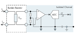
The low-voltage input can be used for current measurement with current clamps, resistive shunts, or burden resistors measuring low-current output from high-precision current transformers.
By adding additional QuantumX modules, even mechanical, hydraulics, or temperature quantities can be measured. The system is freely scalable.
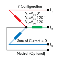
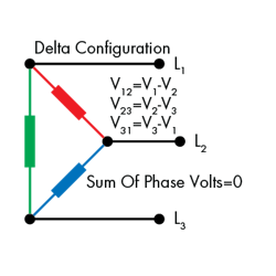
The two most common ways to connect three-phase electric induction motors in industrial applications are the Y or star configuration and Delta configuration. In each of these configurations, there are three voltages (L1, L2, and L3) and three currents, all sinusoidal waveforms, each with a phase difference of 120°.
In the Y configuration, the voltage across the loads is equal to the line voltage, whereas in the delta configuration, the voltage across each load is instead line-to-line. In either case, the voltages and currents should be balanced. The line voltages should all be equal to one another and 120° out of phase with one another.
In the Y configuration, the return path for the current in a particular phase conductor is the other two phase conductors. When properly balanced, the neutral conductor carries little or no current, and in some systems may even be optional. Properly balancing the voltages and currents also helps to reduce vibrations.
To calculate the consumed electric power, the data-acquisition system has to measure the voltage and current of each phase. To do this, you'll need to setup a data-acquisition system with at least six channels—three to measure the phase voltages and three to measure the phase currents.
While you can connect the three voltages directly to the data-acquisition system, you may not be able to measure the current quite so directly. For this purpose, you can use current sensors, such as current clamps or resistive shunts, and read an output voltage. Another option is to use current transformers to lower the current and measure the voltage with a burden resistor plugged into the MX403B
Adding Sensors
When using inductive sensors, be sure to compensate for any phase error or voltage attenuation as part of the measurement calibration process. The data can be found in the sensor datasheet. If, however, this information is not present, it is easy to determine these values. All you have to do is measure the current through a resistive load using the selected sensor and determine the phase shift.
You can then use this value when measuring the motor’s power consumption. This ensures that the measured voltages and currents have the appropriate phase relationship and the power measurement is accurate. Making this calculation is very easy to do with a data-acquisition system, and as a result, you are able to choose a current sensor that has the appropriate size, accuracy, bandwidth, and frequency range.
With accurate voltage and current measurements, you can then calculate the rms voltage and current as well as the power factor. The power factor is a measure of how much the current leads or lags the applied voltage. Mathematically, the power factor is the cosine of phase angle between the voltage and current during the measurement process. The ac power consumed, also known as active power, is the product of the rms voltage, rms current, and power factor.
Some of the applied power is reflected back (or lost) due to energy stored in the load, or due to a nonlinear load that distorts the wave shape of the current drawn from the source. This is called reactive power. A motor with a low power factor draws more current than a motor with a high power factor for the same amount of useful power transferred. The higher currents increase the energy lost in the system. As such, electric motors with a high power factor are more desirable than motors with a low power factor.
Modulating the phase and amplitude of applied voltage to the motor makes it possible to minimize the contribution of reactive power, which, in turn, creates a much more energy-efficient system. A variable-frequency drive or inverter-based drive can make that happen. It simply takes a sine-wave input and load feedback from the motor, which then outputs a pulse-width-modulated sinusoidal waveform instead of a smooth sine wave. The motor basically sees this as a sine wave with a ripple, and because motor windings are inductive, will filter out any high-frequency component. This type of closed-loop control allows the motors to operate much more efficiently.
Some data-acquisition system provides an easy-to-use approach for measuring the efficiency of electrical motors and other electrically actuated systems. Connectivity is simply plug-and-play with provided adapters, and data can be acquired immediately with no programming needed. Data-acquisition systems are able to provide accuracies up to 0.05% and resolution up to 24 bits. They can acquire data up to 100 k samples/s, and stream the acquired raw data to a computer for online analysis.
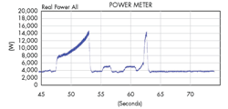
Data-acquisition systems can help troubleshooting by defining custom triggers. For example, a user may set a trigger to take measurements when a system that normally consumes 500 W suddenly spikes to over 1,000 W. Because the system measures both electrical input power and mechanical output power, the user has the data needed to figure out what caused the electrical spike.
In addition, the software is capable of performing a fast Fourier transform (FFT) on the raw data, which can determine harmonics of the signal. Voltage harmonics are mostly caused by current harmonics triggered by nonlinear loads.
Making power-efficiency measurements will not only help you comply with DoE mandates, but also help in creating an efficient electric motor. By analyzing and calculating your system under typical load and operating conditions, you can determine your system’s average power consumption and when power consumption peaks, and subsequently take the appropriate steps to reduce that consumption.
Christof Salcher studied electrical engineering and information technology, graduating from Technical University of Munich, Germany in 1999. Soon after, he worked as an engineering consultant for dSPACE, and in 2004, Christof joined MAGNA Electronics as a team manager. Since 2007, he has worked as international product manager in the test-and-measurement domain, specifying and designing its product QuantumX—a universal data-acquisition system for in-field and lab testing of systems and complete vehicles under development.
