Linear Actuators Accelerate Motion-System Design
This file type includes high-resolution graphics and schematics when applicable.
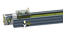
A linear actuator is a combination of linear guides and power-transmission components contained in an assembly. Sometimes these are referred to as a linear motion system, or an actuated system. Designing with a complete actuated linear system can reduce overall machine design and fabrication costs. Standardized actuator products eliminate the effort associated with integrating lower-level components and assemblies, and they contain application-tested and -optimized construction.
The LoPro Linear Actuator product line from Bishop-Wisecarver Corp. is an industry-tested solution for accelerating motion-system design. LoPro actuators are made from standardized sub-assemblies and options that are customized for specific application requirements.
They utilize DualVee Motion Technology for the linear guides, which are double-row angular contact ball-bearing guide wheels that provide smooth and quiet motion over long length. The guide wheels feature 90-degree surfaces that roll on long linear tracks. The tracks can be up to 20 feet long and butt-joined for unlimited lengths. LoPro actuators are produced in user-specified stroke lengths, and motion systems in the 15-meter range are common for long-distance pick-and-place applications.
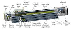
Several drive types are available, including ball screw, lead screw, AT belt, and ANSI roller chain. Power transmission via an AT-style belt provides for a good balance of precision locating accuracy, long travel stroke lengths, and high speed. The AT belt is a high durometer polyurethane belt with internal steel-cable reinforcement. LoPro linear actuators with belt drives include a complete system to support and tension the belt.
The drive end is where a motor or manual hand wheel is attached to a keyed output shaft. The shaft is held with support bearings and holds a toothed pulley. The idler end also contains a toothed pulley and support bearings, but also includes a yoke to apply belt tension. The belt is attached to a wheel plate that includes the linear-guide wheel bearings. Motion is generated at the wheel plate when the drive shaft is rotated.
Looking for parts? Go to SourceESB.
About the Author
Brian Burke
Product Manager
Brian Burke, product manager at Bishop-Wisecarver Group, is passionate about product development and manufacturing. He has an educational background in computer aided drafting and design and manufacturing technology. Brian has more than 10 years of experience in the automation industry with extensive knowledge from the production floor operations to product marketing activities, including CNC machining, lean manufacturing, equipment acquisition and implementation, product literature and catalog development, and trade show expositions.
Voice Your Opinion!
To join the conversation, and become an exclusive member of Machine Design, create an account today!

Leaders relevant to this article: