Engineering Essentials: Tips for Maximizing Cylinder Performance
Fluid power is routinely used in industrial applications, most often with cylinders providing linear motion. Among their advantages, hydraulic and pneumatic power-transmission systems offer: simple and accurate control of force and velocity; a high force-to-weight ratio; constant force or torque output; and safety in hazardous environments, as fluid-power setups present no explosion risk.
Technology-wise, the main competition to fluid-power cylinders is electromechanical linear actuators — for instance, motor-driven ball screws — known for quiet, clean, precise operation and flexible, multipositioning capabilities.
Application requirements usually dictate the most suitable choice. Pneumatic systems perform well where the job demands relatively low force, and lower cost and clean operation are design objectives. Like electricity, compressed air in industrial settings is a bit of a commodity. An air compressor is a common fixture in most plants, which simplifies the installation of pneumatic components. However, the cost of operating an air-powered machine may be higher than comparable hydraulic units.
In contrast, hydraulic designs typically have higher up-front costs for the cylinder, valves, and power unit — but they operate at higher pressures, which equates to higher output forces.
Sizing cylinders
Design engineers should consider factors such as the required force, offset loads, and needed safety factors to properly size an actuator. Oversized pneumatic cylinders consume excessive amount of air and, ultimately, cost more to operate over the long term, compared with right-sized units. On the other hand, undersizing a cylinder can degrade application performance and safety.
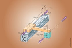
Properly sizing a pneumatic cylinder depends on available air pressure; the size of the load, its orientation relative to the cylinder’s carrier, and its center of gravity relative to the cylinder’s working load point; cycle times; stroke; and the true velocity of the load being moved.
To streamline and simplify the cylinder selection process, and often improve overall accuracy, a number of fluid-power manufacturers have sizing software tools available online. It lets engineers find the right part for the job and test it against different application variables.
In the most common configuration, double acting, routing pressurized fluid into the cylinder’s cap end causes the rod to extend; while routing fluid into the rod end causes the piston rod to retract. In hydraulic setups, fluid on the opposite side of the piston flows into a reservoir. In pneumatic actuators, air simply vents to the atmosphere.
In cases where high forces are needed in only one direction (for example, where a load must be moved and then held at a position for a significant period of time) single-acting cylinders are a suitable alternative. These are either extended or returned by a spring. The former is common for workholding, while the latter is widespread in simple brakes and even complex material-handling tasks.
Regardless of the design, pneumatic-cylinder load capacity is partially based on available air pressure. The cylinder should perform the designated task with a bit of spare capacity. If an application requires the absolute maximum output from a given cylinder, the designer should consider either a larger bore size or a different cylinder style.
Engineers often select a cylinder based only on force capacity, but that can lead to trouble if the actuator itself must support a load. Bending moment becomes an important design factor. If the cylinder rod must support the workload over the length of the linear motion, an overhung load may result. Two factors ultimately determine bending-moment capacity: the strength of the rod to resist deflection and the ability of the linear bearing to support that load.
To address problematic setups with extreme bending moments, turn to guided linear slides. A pneumatic linear slide combines an air-cylinder power source with a guide mechanism that supports the workload over a precise linear path. The most-commonly used guide mechanism consists of a bearing block with two guide shafts attached to a common toolbar. Another option is rectangular units that are guided in two dimensions, so that side and moment loads can be handled simultaneously.
Boosting force
Sometimes operating parameters change after equipment is up and running, and an application subsequently requires more force than a cylinder can produce. If spending time and money to redesign a machine is not a viable option, one solution is to retrofit the cylinder with a booster — a component that provides additional power to an existing underperforming application.
There are three common situations where a booster routinely provides extra force:
• A plant has inadequate air pressure.
• Heavy-duty applications require additional force beyond the cylinder’s capability.
• Designs must compensate for pressure losses.
With only 80 psi available at most plants, some tasks just can’t be accomplished without grossly oversizing components. For example, when a water-bottle manufacturer performs integrity tests, vessels must be pressurized to 175 psi to ensure quality. By adding a booster, designers can double, triple, or even quadruple an actuator’s force to meet application demands.
Boosters are also useful on machines designed for one task, but being repurposed for another that requires more force. From clamping to tube bending, a myriad of specialty applications requires additional force to execute the job correctly. In one such case, a machine designed to form 0.125-in. metal strips performed sluggishly when the product was changed to 0.187 in. Adding a booster solved the problem, leveraging the fact that most cylinders are rated for pressures higher than that normally available in a plant.
Finally, boosters can compensate for pressure loss. When consistent pressure is of the utmost importance, a booster is a must. Pressure can drop during peak periods of compressor demand and, without compensating for this, some applications may suffer. For example, in a newspaper-printing operation, pressure on the rolls must remain at a constant 75 psi for uniform ink distribution. Without a booster to act as a fail-safe, pressure drop could cause quality to suffer and lead to waste.
Note, however, that many directional-control valves are rated for a maximum pressure of 100 to 125 psi. Circuits using a booster can easily exceed this limit, resulting in blown-out seals. So before adding a booster, check the specs of all related components to avoid failure. Likewise some, but not all, pneumatic cylinders are rated to 250 psi and higher to handle extra force.
Also keep in mind that boosters are typically not designed for continuous duty. Systems should incorporate a downstream reservoir, with sizing a function of actuator size and duty cycle. Most boosters are designed to start automatically, shut off at maximum pressure output, and restart when downstream pressure drops.
Other options
If space constraints in a new or retrofit design prohibit a large-diameter cylinder, and a booster is not an option, there are other ways to increase output force. One approach is to stack multiple pistons to create more area within the same bore — in what’s called a tandem cylinder setup. This multistage approach does add to overall length, but provides high reliability.
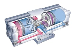
These cylinders act as two single rod-end cylinders connected in line, with each piston interconnected to a common rod as well as a second rod that extends through the rod-end cap. Each piston chamber is double acting to produce high force without an increase in pressure or bore diameter.
Stroke considerations
In the most common cylinder, a single rod nearly as long as the barrel protrudes from the rod-end cap to transmit force and motion. Double rod-end cylinders have two rods (one attached to each piston face) extending through both end caps. These can move two loads simultaneously, eliminating the differential area between the rod side and blank piston side. With equal areas (and cylinder volumes) on both sides of the piston, a given flow produces the same extension and retraction speeds.
However, if a design requires multiple stroke lengths, duplex cylinders are one option. These units have multiple unconnected cylinders; the rod of one protrudes into the nonrod end of the second, and so forth — useful for delivering multiple stroke lengths with one unit.
Teaming a cylinder with a pneumatic proportional valve permits multiple-positioning capability between the cylinder’s minimum and maximum stroke.
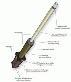
Where total stroke length reaches many feet (even beyond 16 ft in some cases) telescoping cylinders are more suitable. These have several sets of nesting stages that act as both cylinder barrel and piston rod. The stages can either extend simultaneously, or one at a time.
Extending cylinder life
Proper setup can yield big benefits in maximizing cylinder performance. For example, consider temperature. It affects cylinder seals and lubrication, so specify a modified seal if the temperature of the operating environment is particularly hot or cold — to protect the entire installation from failure.
Similarly, caustic washdowns can attack cylinder materials. Here, special finishes and materials are available to reduce the corrosive effect, and special designs can help keep washdown fluid out of the cylinder’s interior.
Finally, poor air quality can accelerate corrosion and shorten seal life. Without a clean, consistent air supply, pneumatic components are prone to premature wear and tear, and eventually failure. But often, real-world shop air is dirty, underlubricated, and provides inconsistent pressure. So when such conditions cause even a single station to require service, an entire manufacturing plant can be disrupted. To prevent such situations, air preparation is one option.
First focus on moisture and debris. While many shops use some degree of filtering throughout the plant, the micron rating may not be high enough for more-sensitive components. Also, moisture can build up in the lines, leading to cylinder corrosion over time.
Second, consider pressure. Available plant air pressure can vary greatly, especially during periods of peak demand. Inconsistent pressure can, for example, cause quality problems by undertorquing components during assembly.
Finally, there’s lubrication. The last thing anyone wants is metal-on-metal contact. Without adequate lubrication, friction can dramatically reduce the life of pneumatic equipment.
To combat these problems, sometimes it’s appropriate to incorporate cylinders that sport special surface finishes or materials. But a complete air-preparation system is generally recommended. This represents a multistep process and generally requires three components: filter, regulator, and lubricator, or FRL. Filters remove debris and moisture and are available in many different micron ratings. Regulators let operators accurately adjust the available pressure for consistency. Lubricators add a fine oil mist to the air to extend the life of the components.
Don’t forget custom
Whether it’s a modification to an existing product or a custom design for a specific application, there are certain considerations when off-the-shelf products won’t do. For starters find a manufacturer that can work closely with you throughout the process; present fresh ideas and suggest workable alternatives when necessary; have a dedication to deliver quality products quickly, adhering to your production schedule whenever possible; and take a strong interest in the outcome of the final project. Suitable manufacturers often adhere to established industry-wide quality control standards when applicable — such as ISO-9001, which provides a uniform framework for quality assurance that is recognized worldwide.
About the Author
Kenneth Korane
Ken Korane holds a B.S. Mechanical Engineering from The Ohio State University. In addition to serving as an editor at Machine Design until August 2015, his prior work experience includes product engineer at Parker Hannifin Corp. and mechanical design engineer at Euclid Inc.
