Some Simple DFMA Magic for Sheet Metal
This article was originally published Sept. 21, 2016. It was updated Feb. 2, 2023.
Engineers designing sheet metal parts and products are often unaware of the difficulties or impossible tasks their designs might present to shop floor personnel. Bends that are too tight, holes to close to the edges of parts and tolerances that can’t be met force engineers to redesign parts to accommodate manufacturing, an expensive proposition.
Unfortunately, research suggests that manufacturers spend 30% to 50% of their time fixing errors and almost 24% of those errors are related to manufacturability. These preventable engineering errors are due to the wide gap between how sheet-metal parts are designed in CAD systems and how they are actually made on the shop floor.
READ MORE: A History of Design for Manufacturing and Assembly
Companies could sidestep these costs and inevitable delays if they adopted Design for Manufacturing and Assembly (DFMA) principles. They would force designers to consider important manufacturability factors while developing sheet metal designs. DFMA focuses on simplifying designs and reducing the parts counts. It suggests using standardizing parts so they can be reused over and over in different applications. DFMA also provides insights on developing designs that are easier to manufacture.
Here are some of the DFMA tips and tactics engineers could apply to sheet metal designs.
Holes and Bends
In sheet metal designs, specifying hole sizes, locations and their alignment is critical. It is always best to specify hole diameters greater than the sheet’s thickness (T). Hole diameters less than the sheet result in higher punch loading and excessive burr. It also leads to slug-pulling when withdrawing the punch, which ultimately affects the life of both punch and metal sheet.
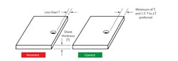
Spacing between holes also matters. It should be at least two times the sheet thickness (2T), if not more. Distance between holes maintains the strength of the metal and prevents holes from deforming during any bending or forming processes.

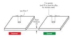
If holes must be near the edge, they should still be at least the distance equal to the sheet thickness (T) from the edge and preferably between 1.5T and 2T from the edge.
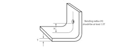
Distances between holes and bends should accommodate the bend radius (H) and be far enough from the bend. Usually, the preferred distance between holes and a bend is 1.5 times the sheet thickness plus the bend radius (1.5T + H). Supplying 3D models without considering these factors increases the chance of change orders from the factory floor.
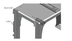
Bend Relief and Tolerances
It is common to see sheet metal designs for parts with modeling mistakes regarding bends and fillets, especially if more than one vendor is involved. This can lead to formed parts looking different from the models they are based on.
READ MORE: A Look Inside the DFMA Toolbox
Engineers designing sheet metal parts should understand the importance of bend relief and how it helps avoid torn metal and that features like beads and flanges serve specific purposes. They reduce the spring-back effect and add stiffness to the final part or product. (Spring-back is the unwanted tendency of sheet metal to retain or go back to its original flat form after the forming process.)
Features such as collars near holes and pierced areas also serve a purpose. They strengthen the metal and let it withstand higher loads. Neglecting these features not only invites ECOs and extends fabrication times, but also significantly increases material scrap.
The metal’s grain structure is critical for avoiding cracks in sheet metal parts that have lugs or tabs that are cut on three sides and bent in or out. Other components are often mounted or clamped to them. The engineer modeling the part needs to understand the grain structure of the metal coil that will be used because lugs formed parallel to the grain direction usually tend to form cracks.
There might be instances in some complex product designs when this rule of thumb might not apply. Still, the recommended practice is to form lugs perpendicular or at an angle less than 45 deg. toward the grain direction. It is likely that engineers would be unaware of this factor while developing the model. Communicating with the fabricator is key.

Designers often deal in the ideal world when specifying tolerance values. However, a part’s function or features, as well as the material, temper and thickness all affect tolerance specifications. Moreover, engineers must consider the fabrication process that will convert the sheet metal into a part, and the die accuracy and its wear during punching operations, to ensure tolerances are accurate.
READ MORE: A Quick Look at DFMA
From the fabricator’s point of view, the punch-to-die clearance is critical because small clearances lead to increased burr height and slug pulling and prematurely wears out the punch. In such cases, the engineer’s tight tolerances increase manufacturing cost.
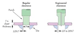
Regular clearance is an exact clearance between die and the punch, and is used, but it also prematurely wears out the punching. Engineered clearance, which is slightly larger than the regular clearance, is preferred because it extends the punch life. Holes punched with engineered clearances have slightly bigger diameters, but damage to the punch is greatly reduced.
Other Tips
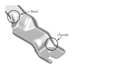
Bends at edges reduce the likelihood of metal tearing.

Putting chamfers at corners and beads on bends increases stiffness and reduces the spring-back effect.
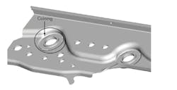
Collars increase the stiffness around pierced areas.

Coining and embossing around flared holes improves a part’s strength and its ability to remain flat.
Benefits of DFMA
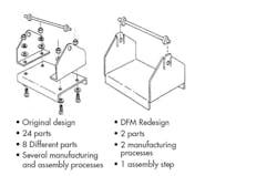
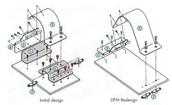
Designers and engineers who adhere to DFMA guidelines strive for sheet metal products with minimal part counts that are relatively easy to manufacture and assemble. The products are also less expensive, and the possibilities of errors and rework are reduced.
Minimizing part count: Part counts can be shrunk by incorporating the functions of two or more parts into a single part. To do this, designers must ask he following questions:
- Do the parts move relative to each other?
- Do the parts need electrical or thermal insulation?
- Do the parts need to be made of different materials?
- Does combining the parts interfere with assembling other parts?
- Will combining parts complicate maintenance?
If the answer to all these questions is no, then a single part may perform several functions. Through this approach, Dell Computer Corp. saved an estimated $15 million by redesigning a computer chassis so it could be used in several lines of PCs. And part count went down by 50% while assembly time fell by 32%.
Ease of assembly: Engineers should develop parts that insert into one another easily and intuitively and always with the proper orientation. And adding self-locking features shorten assembly times and lower parts counts.
READ MORE: DFMA Redesign Leads to Reusable Parts That Withstand the Heat
Usually, it is a good practice to make the first part large and wide to ensure a stable base; smaller parts can then be assembled on top of it. It is also a good practice to design parts so they can be assembled from one direction, rather than multiple directions, which extends assembly times and complicates assembly lines
Ease of manufacturing: Engineers should know the manufacturing capabilities and limitations of the fabricating processes available, as well as the materials compatible with them and their production volumes. Then, to simplify manufacturing follow tips such as:
- Use near-net shapes for molded parts to reduce machining and processing.
- Simplify fixturing by providing large mounting surfaces and parallel clamping surfaces.
- Prevent parts from breaking easily by not giving them sharp corners or points.
- Thin walls, webs, deep pockets, and holes should be avoided so parts withstand clamping and machining without distorting.
- Engineers should know what standard cutters, drill-bit sizes and other tools are available in the shop before designing sheet metal parts.
- Avoid unnecessary features, as they slow production and increase machining times and cost.
About the Author
Voice Your Opinion!
To join the conversation, and become an exclusive member of Machine Design, create an account today!

Leaders relevant to this article: