Download this article in PDF format.
Cracks found in machine and structural components raise two questions: Will the crack cause an immediate failure, and if not, how long until the crack grows large enough for failure?
To address the first question, two methods are used to evaluate cracked components:
- Ductile tearing analysis
- Failure Assessment Diagram (FAD)
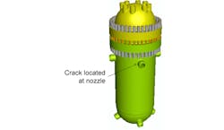
Computing critical flaw sizes helps to ensure damage-tolerant components and set appropriate inspection schedules when combined with fatigue analysis. The historic Shippingport reactor vessel (Fig. 1) provides an example to compare the two analysis methods.
1. Shippingport reactor pressure vessel.
A crack in a pressure vessel is analyzed with quarter symmetry to simplify the model. The top head and flange are omitted, since the circumferential flange is much stiffer than the region around the nozzle. A stress concentration by the base of the nozzle is a good location to examine a postulated crack.
Crack Meshes
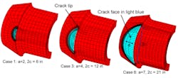
3D crack meshes are generated for a range of crack sizes (FEACrack 2015). Figure 2 shows cutaway views of the surface crack face for three crack sizes. The surface crack sizes are denoted by the crack length (2c) and the crack depth (a).
2. Cutaway view to reveal the surface crack.
A ductile tearing analysis requires a range of crack sizes to compute the tearing modulus, so the crack length-to-depth aspect ratio is kept constant at 2c/a = 3 to create a range of crack sizes. Other crack aspect ratios can be used to develop a full trend of critical crack sizes for shorter to longer crack shapes.
The concentric and radial mesh lines from the crack front are needed to compute the J-integral. For elastic-plastic analysis, there is a set of initially coincident nodes for the collapsed brick elements at each crack front position. The coincident nodes can separate as the load increases, helping to capture crack front blunting.
For the elastic-plastic analysis, the A508 steel material yield strength is 36 ksi, and the tensile strength is 70 ksi (ASME 2010). A Ramberg-Osgood equation is fit to the two tensile values to obtain a stress-strain curve. The Young’s modulus (E) is 30,000 ksi, and the Poisson’s ratio is 0.29. The shell’s outside diameter is 125.75 in., and the thickness is 8.375 in.
Finite Element Analysis (FEA) Results
The elastic-plastic analysis for each crack size uses 20 analysis steps for equilibrium convergence and to provide output sets at each pressure load. The principal stress results were presented for the largest and smallest crack sizes.
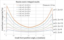
The crack front J-integral values are shown in Figure 3. The plot x-axis is the crack front node position angle, starting at the bottom crack tip; the center of the plot is at the deepest point of the surface crack. As the crack size increases, so do the J values, which is typical for pressure loading causing tensile stress through the vessel thickness.
3. Crack front J-integral results for each crack size.
Ductile Tearing Instability Assessment
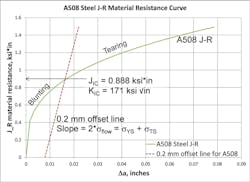
The ductile tearing instability analysis method (Anderson 2005, API 2007, Rowson 2011, and Thorwald 2011) requires a material resistance J-R curve and J-integral results for several crack sizes. The A508 steel J-R curve from API 579 Table F.10 is shown in Figure 4. The J-R curve is described by the power-law equation:
where Da is the crack extension measured from starting crack size a0 to the current crack size a; CT is the tearing coefficient; and nT is the tearing exponent. For A508 steel at 550oF, the coefficient and exponent values are: CT = 3.443 ksi*in, nT = 0.329.
The 0.2 mm offset line shown in Fig. 4 intersects with the J-R curve at the JIc single toughness value, where crack front blunting gives way to ductile tearing behavior. The slope of the 0.2-mm offset line is given by a constant (default of 2 used here) multiplied by the flow stress. The intersection of the J-R curve and offset line is found by iteration.
4. A508 steel J-R resistance curve and single toughness value.
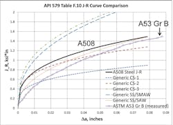
The curves in Figure 5 present a comparison of the A508 J-R curve to other materials. Most are generic carbon and stainless steels from API 579, and the A53 curve is from material testing (Rowson 2011) according to the ASTM E1820 standard (ASTM 2015).
5. J-R curve comparison.
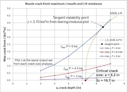
The ductile tearing instability assessment uses the crack front J-integral values at a given load and compares them to the material resistance J-R curve. Figure 6 shows the crack front maximum J values, which occur near the crack tip, for three pressure load cases versus a range of crack sizes, as represented by the crack depth a (plot x-axis), since the 2c/a aspect ratio is kept constant. The label Japp is the “applied” J value from the analysis results.
The Japp result curves in Fig. 6 are obtained by plotting J at the same load value from each crack analysis to get the trend of J versus crack size for comparison to the J-R resistance curve.
6. Tangent instability point used to determine critical crack size.
A starting point for a ductile tearing assessment would use at least three crack sizes—small, medium, and large—to obtain the J versus a trend and compute a tearing modulus. Adding more crack size cases is beneficial because it adds more data points to the curves, ultimately improving the trends and instability assessment.
Imagine the J-R curve in Fig. 6 being shifted left and right along the x-axis by varying a0 until a tangent point is found with a Japp curve. For the maximum pressure load case, a tangent point is found at J = 3.7 ksi*in, corresponding to a starting critical crack size of a0 = 5.2 by 2c0 = 15.7 in.
If the starting crack size is slightly larger, the crack would be unstable, predicting a failure at this pressure. In this case, the Japp and J-R curves would not intersect. If the starting crack size is slightly smaller, the crack would have stable tearing, and the Japp and J-R curves would intersect. Note that the two lower-pressure load cases intersect the J-R curve and would be considered stable for this starting crack size.
There can be a region of overlap in the J versus a curves near the tangent instability point, making visual identification of the tangent point somewhat imprecise. To more precisely locate the tangent instability point, the non-dimensional tearing modulus (T) is computed using:
where the tearing modulus is normalized by the Young’s modulus E and the yield strength; and dJ/da is the derivative of the Japp or J-R curve. Tapp is the tearing modulus computed from Japp, and T-R is the tearing modulus computed from the J-R curve.
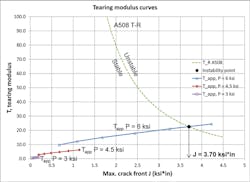
For the Japp curve, a polynomial curve-fit works well to fit the J versus a results and obtain the dJ/da derivative. The Tapp tearing modulus is computed for the three pressure load cases at each crack size a and plotted versus the corresponding J values for those crack sizes in Figure 7.
7. Tearing modulus plot to determine the instability point.
In Fig. 7, points below the T-R curve are stable, and points above the T-R curve are unstable and predict failure. The intersection of the maximum pressure load Tapp and T-R curves is where the slope of those curves is equal (tangent point), and the intersection gives a more definite instability point than on the J versus a plot. For the maximum pressure load case, the critical J = 3.70 ksi*in, which is found by iteration.
The critical J value from the tearing modulus curve intersection gives the y-axis value of the tangent instability point in Fig. 6. Solving the Japp curve-fit by iteration gives the crack size a at the tangent point on the Japp curve. Finally, Equation 1 is solved iteratively for the starting crack size a0 using crack size a and the critical J value at the tangent point.
Comparison to the Failure Assessment Diagram Method
The FAD method (API 2007, Anderson 2005, Tipple 2012, and Thorwald 2016) evaluates a cracked structural component using two non-dimensional ratios—Kr and Lr—to give the assessment point location compared to the FAD curve.
The Kr ratio is the crack front stress intensity (KI) computed using an elastic analysis, divided by the material fracture toughness (KIc). The Lr ratio is the crack front reference stress computed using the J-integral from an elastic-plastic analysis divided by the yield strength. The reference stress calculation relies on the ratio of the total J divided by an extrapolated elastic J to compute both the Lr ratio and the analysis-specific FAD curve. If an Lr, Kr assessment point is below the FAD curve, it is stable; a point above the curve is unstable and predicts failure.
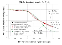
To compare the FAD method to the ductile tearing instability method, the assessment point is computed for the critical crack size obtained from the tearing instability (a = 5.2 by 2c = 15.7 in.). The KIc toughness used to compute the Kr ratio is taken from the J-R curve in Fig. 4 at the 0.2-mm offset line.
Figure 8 shows that the assessment point (black circle) is outside the FAD curve, indicating that the FAD method is more conservative than the tearing instability method. This is expected since the J-R curve has a rising toughness trend to account for stable ductile tearing before failure, while the FAD method uses the single toughness value. The assessment point is near the right side of the FAD, and is to the right of the A508 recommended Lrmax = 1.25 cutoff, indicating that plastic collapse is a possibility. If the default Lrmax cutoff is used, the assessment point is still to the left of that plastic collapse limit.
8. FAD assessment points comparison.
Another way to compare the assessment methods is to compute the critical flaw size using the FAD method and compare that directly to the critical crack size obtained using tearing instability. By varying the crack sizes, the assessment points for critical crack sizes will be located on the FAD curves. One choice is to determine the critical flaw size on the analysis-specific FAD, and another choice is to determine the critical flaw size on the default API 579 FAD. Both critical crack sizes from the FAD are smaller and more conservative than from the ductile tearing assessment.
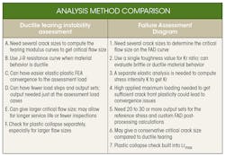
The table below compares information needed by both methods, such as elastic-plastic FEA and a range of crack sizes. Both methods have advantages, depending on the material behavior, desired failure assessment, and material data available. The ductile tearing assessment requires the material J-R resistance curve, which may not always be available. A single toughness value or lower-bound toughness may be easier to obtain. The single toughness value used in the FAD method can come from the J-R curve.
The FAD method needs high-enough crack front plasticity to complete the reference stress calculations, which can cause FEA convergence difficulties if the estimated maximum loading is too high. Often, the needed maximum load is above the assessment load (a design or operating load) and may take some trial-and-error for adequate J plasticity and convergence. The ductile tearing method only needs convergence up to the assessment load of interest, and does not have a crack front plasticity requirement.
For smaller cracks or lower loads, the ductile tearing method may be able to indicate quickly that the crack is stable from just a few analysis cases. A separate plastic collapse check is needed for the ductile tearing assessment, especially when the remaining ligament is small, whereas the FAD method has a built-in plastic collapse check at the Lrmax cutoff.
The FAD and ductile tearing methods from API 579 are single-parameter assessment methods using K or J to characterize the crack front. In some crack cases, a two-parameter approach may be needed to characterize the crack front, in order to also compute, say, the T-stress. ASTM 2899 (see reference 13) uses a function of J and T-stress to determine the instability location along the crack front, which could be used to extend this analysis.
Summary
The ductile tearing instability assessment and Failure Assessment Diagram methods were compared by computing a critical flaw size of a postulated crack in the Shippingport reactor pressure vessel. Elastic-plastic FEA using 3D crack meshes computed the crack front J-integral values needed for both methods. A range of crack sizes was used in both methods to determine the critical flaw size.
The tearing instability assessment uses the J-R material resistance curve, and the FAD method uses a single toughness value. In this example, the tearing instability gave a larger critical crack size compared to the FAD method. Both methods have advantages depending on the material behavior, the desired failure assessment method, and the material data available.
References
1. Abaqus/Standard version 6.14-1, Dassault Systémes Simulia Corp., Providence, RI.
2. Abaqus Technology Brief, TB-060ARCAE-1, “Coupled Thermal-Structural Analysis of the Shippingport Nuclear Reactor Using Adaptive Remshing in Abaqus/CAE,” Revised April 2007, accessed Oct. 2015.
3. Anderson, T. L., Fracture Mechanics, Fundamentals and Applications, 3rd ed., 2005, CRC Press, Taylor & Francis Group, Section 7.4, Section 9.3.3, and Equations 9.51 and 9.52.
4. API 579-1/ASME FFS-1 2007 Fitness-for-Service, Table F.10, page F-67 and Part 9, June 5, 2007, American Petroleum Institute and American Society of Mechanical Engineers, API Publishing Services, 1220 L Street, N.W., Washington, D.C. 20005.
5. ASME Boiler and Pressure Vessel Code, Section II, Part D 2010 Table U, p. 464 and Table Y-1, p. 544, American Society of Mechanical Engineers, Three Park Ave, New York, NY 10016.
6. ASTM E1820-15, “Standard Test Method for Measurement of Fracture Toughness,” ASTM International, 2015, 100 Barr Harbor Drive, PO Box C700, West Conshohocken, PA 19428.
7. FEACrack, Version 3.2.27, 2015, Quest Integrity USA, 1965 57th Court North Suite 100, Boulder, CO 80301, www.questintegrity.com.
8. Rowson, Q., and M. Rock, “Comparison Between Ductile Tearing Analysis and Linear Elastic Fracture Mechanics Analysis,” NAFEMS World Congress, May 2011, Boston, MA.
9. Thorwald, G., and M. Rock, “Ductile Tearing Analysis of a Custom Pipe to Flange Nozzle Using 3D Crack Meshes,” NAFEMS World Congress, May 2011, Boston, MA.
10. Thorwald, G., and L. Parietti, “Leak-Before-Break Assessment of a Cracked Reactor Vessel Using 3D Crack Meshes,” Proceedings of the ASME 2016 Pressure Vessels and Piping Conference, PVP2016, July 17-21, 2016, paper no. PVP2016-63910.
11. Tipple, C., and G. Thorwald, “Using the Failure Assessment Diagram Method with Fatigue Crack Growth to Determine Leak-before-Rupture,” SIMULIA Community Conference, May 2012, Providence, RI.
12. Wikipedia, “Shippingport Atomic Power Station,” accessed Dec. 17, 2015.
13. ASTM E2899-13, “Standard Test Method for Measurement of Initiation Toughness in Surface Cracks Under Tension and Bending,” ASTM International, 2013, 100 Barr Harbor Drive, P.O. Box C700, West Conshohocken, PA 19428.
14. Thorwald, G. and J. Wright, “Ductile Tearing Instability Assessment of a Cracked Reactor Pressure Vessel Nozzle for Larger Critical Crack Size Compared to the FAD Method”, SIMULIA “Science in the Age of Experience” conference, Boston 2016.
About the Author
Greg Thorwald
Principal Consulting Engineer
Greg Thorwald uses FEA for structural, fracture, and fatigue crack growth assessments in a variety of fitness-for-service consulting projects. He is the lead developer of the FEACrack software, an automated parametric 3D crack mesh generation program that creases FEA input files used to compute crack front stress intensity and J-integral values needed for assessments. Greg earned a Ph.D. in aerospace engineering from the University of Colorado.

