New Fasteners Attach Aluminum Body Panels to Ultra-High-Strength Steel
In August 2012, the federal government released its future CAFE (Corporate Average Fuel Economy) targets. They nearly doubled, going from approximately 27 mpg in 2012 to 54.5 mpg by 2025. This does not mean we should expect all vehicles to get these gas mileage ratings. It is not that simple. In fact, CAFE measurements are complicated and are lab-generated figures, not a measure of actual vehicles’ performance. However, what is clear is that between now and 2025 we can expect automotive OEMs to significantly improve their fleets’ gas mileage. To do this, they will make a large, unprecedented investment in resources to bring new weight savings and operational efficiency improvements to their cars and trucks.
Although weight savings is a multifaceted topic, perhaps the most interesting area of development is in weight savings to the body and frame of vehicles. Many will remember the 2015 game-changing release of the all-aluminum Ford F150. Ford engineers took out a whopping 700 lb from the previous model by replacing steel structural beams and sheet-body panels with aluminum extrusions, hydro-formed beams, and sheets. This was no easy task as it forced Ford engineers to rethink the way they manufactured vehicles. It was also clear that it would not have been possible without many advances and innovations in enabling technologies.
As successful as this approach has been, it is unfortunately not the answer for every future passenger car and light truck. In fact, it may not be the answer for most, since it is a “premium” solution and requires a vehicle with enough cost elasticity to support the added price. It also raises challenges with regards to meeting federal strength requirements. Therefore, an alternate or in some cases hybrid strategy gaining momentum is to pair aluminum panels with high- and ultra-high-strength steel substructures. These high-strength steel structures can range anywhere from about 600 MPa on the low end to about 1,800 MPa on the high end. The advantage of these high-strength structures is that they are relatively cheap and can provide the same or often greater strength with thinner cross-sections than their lower-strength counterparts. These thinner cross-sections equate to lower weight and thus the designer gets “two for the price of one” —higher strength and lower weight.
Unfortunately, these advantages come with some trade-offs, especially when pairing aluminum with high-strength steel. In these instances, traditional fastening methods break down. Because of the dissimilar metal pairing, traditional thermal joining methods don’t work, and because of the high-strength nature of the steel component, traditional riveting and clinching technology often doesn’t work.
Fortunately, man is creative and where challenges exist, solutions often follow. That is precisely the case of a new fastening technology by EJOT GmbH (www.ejot-usa.com) called EJOWELD. EJOWELD fasteners employ a friction-welding fastening element to pierce the aluminum top sheet, compress the joint, and fasten it together with friction welding. There are two distinctly different versions available.
The Composite Friction Pin (CFP) can fully pierce both the aluminum top sheet and the lower high-strength steel sheet up to 1,000 MPa. The second version, Composite Friction Fastener (CFF), is a partially piercing, friction-welding element. The CFF element pierces the aluminum top sheet and friction welds to the bottom high-strength steel sheet with strength levels up to 1,800 MPa. In practice, this means the CFP requires only one-sided access for installation while the CFF needs two-sided access.
Although the CFP certainly has potential for automotive applications, particularly where only one-sided access is available, the CFF is likely to find more use for automotive applications. This is a fully integrated system, meaning the technology is as much about having the proper installation equipment and protocols as it is about the fastening element itself.
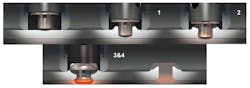
The figure above shows how the CFFs are installed. In step one, the specially designed fastening element is turned at high rpms while a modest axial load is applied. This effectively lets the fastening element pierce the aluminum top sheet and proceed all the way through until it meets the lower high-strength steel sheet. In step two, the fastener continues to rotate at high speed with some axial pressure to “clean” and prepare the high-strength steel sheet for friction welding. This is critical in getting a quality weld.
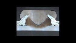
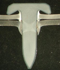
In step three, the axial load increases so heat generated by the friction of the fastening element turning against the steel sheet increases rapidly. The heat creates a plastic zone at the tip of the fastening element and in the affected area of the steel sheet. In fact, no pool of molten metal is created while these two plastic regions are welded together. The axial load compresses the fastening element into a secure welded interface between the fastening element and the steel sheet. Additionally, the axial load compresses the joint together so that it is solid and tight. The final step, number 4, involves a short dwell time to let the joint cool sufficiently before the axial load is released. The figure below shows a cross-sectional example of one of these completed joints. It clearly shows how the friction element “curls up” and bonds to the high-strength steel sheet as a result of the axial load exerted when the material is in its plastic state.
CFFs do require two-sided access. This means installation equipment has a driving unit on top and an anvil attached to a C-frame on the bottom. Although static (floor-standing) units are available, the technology is more likely to be applied by robots similar to those used in body shops to make spot welds. The installation cycle time should be similar to other automated joining technologies such as self-piercing rivets and clinching technology.
Often, these aluminum/steel joints are designed with an adhesive between the aluminum and steel. This serves several purposes. The two primary purposes are to add to the bonding strength of the two components or sheets and to provide dielectric separation between the dissimilar materials. An added advantage is that these adhesive layers are not harmed by the joining process and presence in the joint stack does not hurt process or quality of the ultimate weld. Therefore, designers need not make any special provisions to provide an adhesive free area for this fastening element to work.
Naturally there are process limitations. The thickness and strength of the upper material being pierced is one factor, as is the thickness and strength of the lower component. As a general rule of thumb, and this is subject to variation from application to application, the top aluminum sheet must be no thicker than 7 mm and the lower, high-strength steel sheet must be at least 1 mm thick.
The fastening elements themselves are designed to be as uniform as possible. They are all identical in diameter and head style. They vary from one another in three distinct areas: length to accommodate different stack heights; point style; and fastener strength. The point and strength variants are available to optimize performance depending on application-specific details. In particular, the available “polygon point” may be employed when piercing thicker aluminum sheet or castings and the higher-strength version of the fastening element may be used when the top or bottom sheet are also higher-strength materials.
CFPs work in a similar manner except they have sharp points to let the fastening element pierce both the upper and lower sheet. The welding process is conceptually the same, except the weld interface is between the sides of the fastening element and the extrusion in the high-strength steel sheet created when it is pierced.
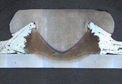
The obvious advantage of a CFP is that it requires only one-sided access. This can be a significant advantage for designers when they can’t get installation equipment into position on both sides of the components being fastened. Unfortunately, the CFP version is limited in that it only works in materials up to about 1,000 MPa. Above this strength, the steel component is too strong and hard to effectively pierce. The figure below shows the cross-section of a CFP joint.
As interest continues to grow in developing composite structures of aluminum and high-strength steel, designers will need to reinvent the way they join these materials. Although there are several methods currently available to join steel and aluminum, the list of available technologies isn’t very long. EJOT’s EJOWELD fasteners are a promising way of doing this and will likely garner the attention of automotive designers and engineers pressed to find better ways to join aluminum with high and ultra-high strength steel.
About the Author
Laurence Claus
Laurence is President of NNi Training and Consulting Inc. He holds a BSME from the University of Illinois, is a Certified Six Sigma Black Belt, and has almost 30 years of experience in the fastener industry. Prior to forming NNi Training and Consulting Inc., he was Vice President of Engineering with a prominent automotive fastener manufacturer. He regularly contributes to industry fastener standards activity by currently serving on multiple fastener standards committees, ASME B18, ASTM F16, ISO TC 2, and the SAE Fastener Committee and until recently on the National Aerospace Standards Committee (NASC) as a Technical Advisor. He is very engaged with the Industrial Fasteners Institute and coordinates their in-house training activities.
Voice Your Opinion!
To join the conversation, and become an exclusive member of Machine Design, create an account today!

Leaders relevant to this article: