Roller Chains and Planetary Gearboxes Yield Accurate, Efficient Motion Control
Durable gears for high-speed or high-power machinery are often complex to design, so mechanical engineers tend to shy away from them and instead rely on electronic controls and toothed belts. However, for dedicated high-speed machinery, gears are the best method in terms of low energy losses, high accuracies, and low play.
Modern engineering has also led to advancements that make gearboxes of all types much smaller than they once were. For example, advanced machining for making gears and shafts means closer possible fits for gear teeth. And face mounted gearboxes today may extend as little as 2.5 in. from the motor and weigh up to 50% less than most commercially available gearboxes, depending on model, power, gear ratio, and the use of aluminum housings.
One of the major technological changes has been the evolution from standard parallel axis gear trains, to planetary gear trains, to planetary gear trains that use roller gears. How do they compare to one another?
Here’s an analysis of a single planetary gearset. One of the planetary gearsets has a roller gear with 72 teeth and a sun gear with 30 teeth. Designers can get lots of different gear ratios out of this gearset. Also, locking any two of the three components together locks up the whole device at a 1:1 gear reduction. Notice that the first gear ratio listed (Case A) is a reduction; output speed is slower than input speed. The second (Case B) is an overdrive; output speed is faster than input speed. The last is a reduction again (Case C), but the output direction is reversed. There are several other ratios that this gearset can deliver.
Parallel Axis to Planetary Gear Trains
In a simple parallel-axis gear train, each of the meshing gears has its own axis and all the axes are parallel. The load is passed from gear to gear, so each gear and engaged tooth see roughly the same load. The train ratio for a simple parallel-axis gear train is the ratio of the number of teeth on the input gear to the number of teeth on the output gear. These gearsets rely on a small number of contact points to transfer the driving force (load). That means all the load gets concentrate on just a few contact points, making the gears wear quickly and sometimes crack.
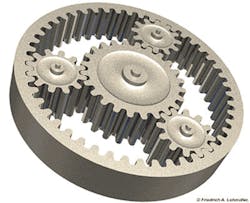
Any planetary gear set (also known as an epicyclic gear set) has three types of gears: sun, ring, and planet gears. The sun and planet gears mesh with each other and rotate about each other inside a ring gear. Each of these three components can be the input, the output, or be held stationary. Choosing which piece plays which role determines the planetary gearset’s ratio.
In a typical application, the drive power connects to the sun gear. The sun gear then drives the planetary gears assembled within the external roller gear ring. The whole set of the planetary gear revolves on its own axis and along the external roller gear ring where the output shaft connects to the planetary carrier for speed reduction. A higher reduction ratio can be achieved by doubling the multi staged gears and planetary gears.
Shown is a traditional planetary gear head with three planetary gears and a ring gear. The solid ring gear requires machining time and cost to create and is heavier than a roller chain, which is used in Gearing Solutions more recent gearset designs.
This style of gearbox is used in conveyors, food processing equipment, material handler equipment, mixer drives, pulleys, pumps, wind energy turbines, and more. Unlike traditional parallel gears, a planetary gear drive has several contact surfaces spread between several gears. Altogether, they have a larger contact area than parallel gears and can distribute loads evenly around the central axis. They also share any instantaneous impact loads, so they better resist damage from higher torques. The housing and bearing parts are also less likely to be damaged and crack from high loading.
The load in a planetary gear train is also shared among several planets; therefore, torque capability is greatly increased. The more planetary gears in the drive, the greater the load ability and the higher the torque density. Planetary gear trains also provide stability due to an even distribution of mass and increased rotational stiffness. Torque applied radially to the gears of a planetary gear train is transferred radially by the gear, without any lateral pressure on the gear teeth.
Planetary gear trains can have higher power densities compared to standard parallel axis gear trains. They are also more compact, provide multiple kinematic combinations, and have purely torsional reactions. They are also efficient. The efficiency loss in a planetary gear train is typically about 3% per stage. This ensures that most of the energy put in (about 97%) gets transmitted through the gearbox rather than being wasted on mechanical losses.
Disadvantages include high bearing loads, constant lubrication requirements, inaccessibility, and design complexity.
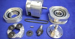
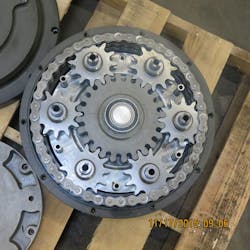
This gear drive from Gearing solutions uses six planetary gears and roller chain.
Adding the Rolling Ring
In the latest innovation, the planetary gear set’s ring gear has been replaced with a roller chain. Also known as a bush roller chain, this is the chain drive commonly used to transmit mechanical power on many kinds of machinery. One of the most common examples is the bicycle chain. It consists of a series of short cylindrical rollers held together by side link and is usually driven by a toothed wheel or sprocket. They are simple, reliable, and efficient.
There are actually two types of links alternating in the bush roller chain. The first type are inner links with two inner plates held together by two sleeves or bushings upon which two rollers rotate. Inner links alternate with the second type, the outer links, and they are made up of two outer plates held together by pins passing through the bushings of the inner links.
The roller chain design reduces friction compared to simpler designs, resulting in higher efficiency and less wear. The original power transmission chain varieties lacked rollers and bushings, with both the inner and outer plates held by pins which directly contacted the sprocket teeth; however, this configuration exhibited extremely rapid wear of both the sprocket teeth and the plates where they pivoted on the pins. The addition of rollers surrounding the bushing sleeves of the chain provide rolling contact with the teeth of the sprockets, resulting in excellent resistance to wear of both sprockets and chain. There is even very low friction, if the chain is sufficiently lubricated. Continuous, clean lubrication of roller chains is of primary importance for efficient operation as well as correct tensioning.
Developing a planetary gear that uses a roller chain to form the internal gear allows for a more compact gearset and the option to use lightweight aluminum casings. The chain provides a wide range of sizes and ratios. For example, if using only a sample of 27 to 100 pitches, nine chain sizes, and 10 ratios, 657 sizes can be configured. Each ratio has its own set of variables, creating thousands of possible combinations. This lets the gearset maintain high levels of energy with minimal energy loss. Newer devices also require less electricity or fuel to operate, which helps increase efficiency.
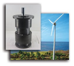
QED Wind Power’s Phoenix 20-kW wind turbines use lightweight, compact, and efficient gear drives from Gearing Solutions to control the yaw of the turbine and keep its blades facing the wind.
Wind Turbines and Yaw Drives
In keeping with the Betz limit, wind turbines can’t harness more than 59% of the wind’s kinetic energy. (If a wind turbine was 100% efficient, there would be no wind left to turn the blades). To increase electrical generation and get as close as possible to that 59% limit, wind turbines rely on yaw drives to point the blades in the direction of the wind. Even with the drives, however, utility-sized wind turbines only get to within 75% to 80% of the Betz limit.
QED Wind Power manufactures the Phoenix 20-kW wind turbines which generate up 50,000 kw-hr annually (assuming a 20-knot wind), enough to power a mid-sized farm or up to eight homes. Yaw drives from Gearing Solutions, which keep the blades turned into the wind, are a critical factor in keeping QED’s turbines turning and making as much electricity as they can.
When QED began looking into redesigning its 20 kW turbine, the components were all made in China. The team wanted American-made parts to ensure quality control and better access to repair parts. QED got its wish, and the Phoenix is a veritable tour of American manufacturing: blades from Texas, meteorological sensors from Oregon, and the yaw drive from Gearing Solutions in Ohio.
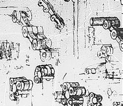
These 16th Century sketches suggest that da Vinci had theorized, if not invented, roller chains long ago.
QED talked with several yaw drive suppliers before choosing Gearing Solutions, but they wanted to sell the team off-the-shelf products which could not take full advantage of the design or supply their specific needs. The engineering staff at Gearing Solutions talked with QED several times before coming up with a custom prototype that would meet its needs.
The prototype had a stronger, more durable shaft and could use a three-phase 1.5-hp motor as the drive motor. The drive was also designed to use grease discs rather than gear oil to simplify maintenance. After several months of testing and revisions in shaft size and material, the new yaw drive was ready.
It combines roller-gear technology with innovative gear construction to optimize the gearbox and minimize size. It is 50% shorter than standard gearboxes and can handle over 30 hp. With the addition of an internal roller gear, driver, and several planetary gears, the new drive handles loads more than three times the size of the earlier drive, and aluminum housings make the drive 50% lighter, lowering the weight-to-torque ratio and increasing the power-to-weight ratio. The lower weight simplifies installation and repairs—both critical when working at height in a tight space. The smaller size also lets the turbine’s nacelle be lighter and more aerodynamic.
Despite their lighter weight, the yaw drives are still durable enough to provide years of trouble-free service. Many have been in continued service for more than five years with no downtime.
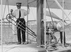
The Wright brothers used roller chains to transmit power from the turning engine shaft to the propellers. That is not unusual considering they ran a bicycle shop and were likely familiar with the technology.
Gears: A Timeline
- 150 to 100 B.C., Greece. The Antikythera mechanism is made with more than 30 gears. It was believed to be used for astronomical calculations.
- 4th Century B.C., China. Early examples of gears are found in the Zhou Dynasty.
- 50 A.D., Egypt. Gears appear in the designs of mathematician and engineer Heron of Alexandria.
- 1206 A.D., Turkey. Ismail al-Jazari, a well-educated man, mentions a gearbox-like arrangement in his book, The Book of Knowledge of Ingenious Mechanical Devices.
- 1510, Italy. Leonardo da Vinci sketches a roller chain.
- 1817, Great Britain. Watt and Boulton Engine use a gearbox with two gears and a governor to maintain rotational speed.
- 1880, Great Britain. Hans Renold invents the bush roller chain for transmitting mechanical power.
- 1881, France. Dion-Bouton begins manufacturing gearboxes for steam cars.
- 1898, France. Inventors Louis-Rene Panhard and Emile Levassor develop the first gear and drive shaft assembly used to power a manual transmission.
- 1904, U.S.A. The Sturtevant brothers of Boston invent the “horseless carriage gearbox.” Unfortunately, manufacturers then did not have the metals we do in the present day, and the gears are given to abrupt shifts that led to transmission failures.
- 1908, U.S.A. Henry Ford comes out the with Model T, featuring gears that function using a planetary gearbox.
Dave Lally is vice president and general manager of Gearing Solutions.
