This article was updated May 24, 2023. It was originally published Oct. 10, 2000.
Noise and vibrations in power transmission devices—both those that use linear, reciprocating motion and rotational motion—present several problems. Noise, for example, can torment nearby workers and potentially damage their hearing for life. And vibrations can damage equipment and lead to catastrophic equipment failures.
Here are some tips for reducing noise and vibrations and the problems they create.
Controlling Them
There are two steps to take to control noise and vibration:
Minimize them. This can be accomplished by:
- Balancing rotating components.
- Reducing the mass of reciprocating members.
- Loading the driven device as uniformly as possible.
- Incorporating a soft-start device to minimize start-up shock.
Accommodate them. Once vibrations are minimized, the next step is to reduce their harmful effects. Here, the key issues are the offending machine’s design and the choice of drive coupling.
Vibrations can be amplified or isolated depending on the machine’s mass and stiffness characteristics. The main parameter to control is the relationship between the machine’s natural and disturbing frequencies.
Natural frequency is the rate at which a spring-mass system vibrates when unrestrained. All machines have a natural frequency that is a function of their stiffness and inertia characteristics.
If a machine operates at or near its natural frequency, the amount of transmitted vibration increases the chances of dramatic and catastrophic failure if it operates at this frequency for only a short time. If the disturbing frequency increases above the natural frequency, vibrations decrease. Eventually the machine enters a region where transmitted vibrations are lower than input vibrations. This is called the isolation region. All machines, both rotational and linear, should be designed to operate in this isolation region.
Damping and Isolation
When discussing vibration and noise, two topics often arise: damping and isolation.
- Damping dissipates vibrational energy by converting mechanical energy into thermal energy.
- Isolation reduces transmitted vibration by storing energy then slowly releasing it.
In many cases, it is impossible to add enough damping to reduce peak transmitted vibrations to safe and acceptable levels. If so, engineers could ensure the natural frequency is far enough below the disturbing frequency that transmitted vibrations are minimized.
Couplings to the Rescue
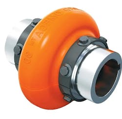
Drive shaft couplings with flexible elastomer components are commonly used to reduce the transmission of noise and vibration as well accommodate shaft misalignments. Elastomers are elastic rubber-like polymers that can be thermosets or thermoplastic. Common ones include natural rubber, polyurethanes, silicone and neoprene.
These couplings let the machine handle relative motions between the driving and driven shafts. When a torsional pulse is transmitted to the coupling, it gets absorbed and momentarily stored as potential energy. That energy is released to the driven shaft over a period of time corresponding to the drive’s natural frequency. In well-designed drives, the natural frequency is lower than the disturbing frequency by at least 30%.
Under these conditions, it takes more time to release the energy than to absorb it. Because the same amount of energy is transmitted over a longer period of time, the shock pulse is lowered, resulting in a smoother-running machine.
Specifying a Coupling
Here’s a simplified four-step method for selecting an elastomeric coupling that will minimize the transmission of noise and vibration.
Determine the disturbing frequencies. For a gasoline or diesel engine, the disturbing frequency (Fd )is obtained thusly:
For a 4-stroke engine: Fd = (N × S)/ 2 x 60
For a 2-stroke engine: Fd = (N × S)/60
where Fd is the disturbing frequency (Hz), N is the number of cylinders, and S is speed (rpm).
For electric motors, the disturbing frequency is:
Fd = (N × S)/60
where N is the number of stator poles and S is the speed (rpm).
To protect against start-up shock, measure the time (in seconds) it takes for the machine to come up to speed. This is the shock pulse duration, T. Convert this into a disturbing frequency by using the formula Fd = 1/2T.
For torsional disturbances created by the driven device, determine the disturbing frequency by estimating the number of load applications per revolution and multiply it by the shaft speed.
Determine the inertia. Divide the driven mass into a series of simplified geometric sections. Then, use standard formulas from engineering textbooks to estimate the inertia of each section. The sum of these inertias is the driven mass’ inertia.
For circular discs or cylinders, the mass moment of inertia is:
J = (π × d4 × L × D)/32g
where J is the mass moment of inertia (in.-lb-sec2/rad), d is the cylinder’s outer diameter (in.), L is the cylinder’s length (in.), D is the material’s density (lb/in.3) and g is the acceleration due to gravity (386.4 in./sec2)
Determine the maximum allowable natural frequency (Fn). Use the following formula. Keeping (Fn) below the disturbing frequency (Fd ) in accordance with this formula prevents torsional vibrations from being amplified and reduces the transmission of vibration and noise.
Fd = (Fn)/1.414
Determine the required coupling spring rate. Use:
K = J × (2π × Fn)2 in.-lb/rad
where K, the required spring rate, can be converted to in.-lb/deg by dividing it by 57.3.
After the design team calculates the required spring rate, it can select the coupling with the needed required torque, speed and misalignment capabilities. A properly selected elastomeric coupling can reduce transmitted torsional vibrations by up to 90%.
RELATED
Design by Objective: Vibration & Noise
Damping Materials Quiet Boat Noise and Vibration
Choosing the Best Vibration Sensor
Noise Prediction for Moving Mechanisms Using Coupled MBD-Acoustics Analysis

