How to Select the Right Brushless Motor
This file type includes high resolution graphics and schematics when applicable.
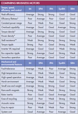
Engineers have several choices to make when selecting brushless motors for their latest designs. Making the wrong choice can doom the design to mediocrity and failure in the marketplace. So to ensure engineers and design teams choose the right brushless motor for their projects, here’s a concise rundown of the benefits and downsides of the four most popular varieties: the AC induction motor (IM), permanent magnet motors (PM), synchronous reluctance motors (SynRM), and switched reluctance motors (SRM).
AC induction motors
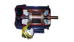
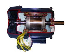
AC induction motors (IMs) have long been the workhorses of industry, and with good reason. They combine reasonable performance with simplicity. They can also be operated directly from ac power supplies, a feature that was important in the past.
Today, advanced power electronics and digital signal processing make it relatively inexpensive to vary the speed of IMs. And modern control algorithms let IMs serve where costly brush motors were once required. The resulting energy savings lead directly to increasingly important financial and environmental benefits. That’s why controlled IMs are easy to find in diverse and cost-critical applications such as electrical vehicles and washing machines, as well as in the industrial world of pumps, fans, blowers, and material handling.
An IM creates torque through the interaction of its rotating stator field with currents induced in rotor conductors. But the currents heat the rotor, reducing efficiency and bearing life. Replacing traditionally aluminum rotor conductors with copper versions help somewhat, but these are costly and may prohibit direct-on-line starting.
The stator’s electrical time constant is long; so to ensure acceptably quick responses to changes in load or speed, it’s usual to operate the motor at constant magnetic flux up to the “base” speed. Unfortunately, associated magnetization losses are then present regardless of how hard the motor is working, resulting in poor light-load efficiencies. Automatically reducing the stator flux at low torques to solve this is possible, but only if rapid control responses are not essential.
At speeds above the base speed, the stator field weakens because of limited supply voltage, so controlled IMs typically deliver constant mechanical power. Efficiency falls quickly, however, because parasitic inductance causes the rotor current to lag behind the rotating field, so more rotor current is needed for a given torque. Consequently controlled IMs are limited to constant power speed range (CPSR) of about 2:1.
Applications requiring a wider CPSR, such as machine tools and vehicle traction, can be met by reducing the number of winding turns and discarding the excess torque capability at lower speeds. Higher stator currents then make for more expensive and less efficient inverters.
A final note of caution: IM name-plate efficiencies are quoted for pure sine-wave operation. In the real world, inverters deliver pulses that only approximate sinusoidal current. Design teams should note that overall system (motor and inverter) efficiency will be less than the product of figures quoted individually for the motor and inverter. Higher carrier frequencies help, but gains in motor performance come at the cost of higher inverter losses. One solution – placing filters between the inverter and motor – is expensive and introduces additional power losses. Plus the filters are relatively large.
Another drawback to AC induction motors is that their stator windings are distributed throughout many slots in the stator core. This means long end-turns which waste space and energy. As a point of interest, the need for inverters disqualifies all but IMs from being sold as IE4 or IE4 class. The current European standard (IEC60034) specifically excludes any motors requiring electronic control.
Permanent Magnet Motors
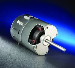
Permanent magnet motors (PMMs) generate torque through the interaction of stator currents with permanent magnets on or within the rotor. Surface rotor magnets are common in small, low-power motors for IT equipment, business machines, and automotive auxiliaries. Interior magnets (IPM) are common in larger machines such as electric vehicles and industrial motors.
In PMMs, the stator may use concentrated (short-pitched) windings if torque ripple is not a concern, but distributed windings are the norm in larger PMMs.
Because PMMs don’t have mechanical commutators, inverters are essential to control the winding current.
Unlike other types of brushless motors, PMMs require no current to support their magnetic fields. Consequently, PMMs deliver the most torque per volume and may be the best choice if small size or light weight is important. No magnetization current also means higher efficiencies at the “sweet-spot” load — i.e., where the motors perform best.
The most obvious advantage of a PMM is high cost. High performance PMMs use magnets made from transition metals such as neodymium and dysprosium. These materials are scarce and come from geopolitically unstable countries, resulting in high and volatile prices.
Furthermore, although permanent magnets bring performance benefits at lower speeds, they are also something of a technical “Achilles’ heel.” For example, as a PMM’s speed increases, its back EMF approaches the inverter supply voltage, making it no longer possible to control winding current. This defines the base speed of a generic PMM and in surface-magnet designs usually represents the maximum possible speed for a given supply voltage.
At speeds greater than the base speed, IPMs use active field weakening in which the stator current is manipulated to deliberately depress magnet flux. The speed range over which this can be reliably implemented is limited to about 4:1. As before, this limitation can be side-stepped by reducing winding turns and accepting greater costs and power losses in the inverter.
The need for field weakening is speed-related and the associated losses arise regardless of torque. This reduces efficiency at high speeds, especially at light loads. This is serious in electric vehicles where cruising at freeway speeds inevitably involves field weakening. PMMs are often favored for EVs, but the efficiency benefit is questionable when computed over real-world driving cycles. In an interesting side note, at least one prominent EV manufacturer has switched from PMs to induction motors.
Other disadvantages of PMMs include the fact that they are notoriously difficult to manage under fault conditions due to their inherent back-EMF. Current continues to flow in winding faults as long as the motor rotates, even if the inverter is disconnected, causing cogging torque and overheating, and both can be hazardous. Loss of field weakening at high speeds, for example, due to inverter shut-down, leads to uncontrolled generating and the inverter DC bus voltage may rise to dangerous levels.
Operating temperatures are another significant limitation for all PMMs except those outfitted with samarium-cobalt magnets. And high motor currents, which can occur due to inverter faults, can lead to demagnetization.
Maximum speed for PMMs is limited by mechanical magnet retention. If a PMM is damaged, repairing it usually entails returning it to the factory because of the difficulty in safely extracting and handling the rotor. Finally, recycling at end-of-life is also troublesome, although the present high value of rare-earth materials may make this more economically viable.
Despite these disadvantages, PMMs remain unsurpassed in terms of low-speed and sweet-spot efficiencies, and they are useful when size and weight are critical.
Synchronous Reluctance Motors
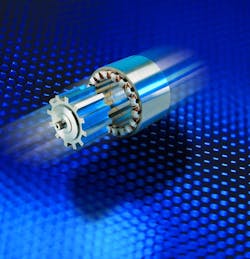
Modern synchronous reluctance motors (SynRMs) are always inverter-fed and use the same type of distributed-wound stators as IMs. The rotors, however, are laminated steel with punched slots so they can easily be magnetized in one axis, less so in the other. The tendency of these rotors to align with the rotating stator field creates torque. Like a PM, SynRMs are self-synchronous, meaning the inverter synchronizes stator energization to the rotor angle and speed.
The principal benefits of SynRMs are their negligible rotor losses compared to IMs. So with careful design and control, SynRMs will be able to meet the motor efficiency guidelines in forthcoming European IE4 and NEMA super-premium standards while avoiding the need for magnets. Reduced heat in the SynRM improves torque and power densities relative to IMs and lets them be typically one frame size smaller for a given rating. These motors are also quiet, thanks to their low torque ripple and vibration levels.
A little-discussed downside of SynRMs is their low power factor compared to IMs, so that significantly more inverter current is needed for a given mechanical power level. This increases costs and inverter power losses so that although SynRM motor-only efficiency may be good, the benefits at the system-level benefits are less convincing. Standards presently discuss motor-only efficiencies, and designers should probe carefully into likely overall system performance.
The need for complex rotor laminations, with their punched flux barriers, makes SynRM rotors difficult to manufacture, somewhat fragile, and therefore unsuited to high-speed operations.
Synchronous reluctance motors are well suited to a wide range of industrial applications which do not require large overloads and high speeds, and are also becoming increasingly offered for variable-speed pumps due to their efficiency.
Switched Reluctance Motors
Some current is needed to support the SRM’s magnetic field, resulting in lower torque densities and sweet-spot efficiencies than PMs. However, like SynRMs, an SRM is typically one frame size smaller than a comparable IM.
A major advantage of SRMs is that field weakening occurs naturally when excitation is reduced without loss of efficiency. This makes wide CPSR (greater than 10:1) possible without difficulty. Efficiency remains good at elevated speeds and light loads, and SRMs can deliver remarkably constant efficiencies across a wide range of operating conditions.
SRMs are also notably fault tolerant. Without magnets, there is no uncontrolled torque, current under winding fault conditions, nor uncontrolled generating at high speeds. Furthermore, because the SRM phases are electrically independent, the motor can, if desired, operate at reduced output but with increased torque ripple when one or more phases are inoperative. This can be useful if the designers want fault tolerance and redundancy.
SRM’s simple construction makes them durable and inexpensive to manufacture. No expensive materials are needed and the plain steel rotor is well-suited to high speeds and harsh environments. And the short-pitched stator coils reduce the risk of winding shorts. Furthermore, end-turns can be short, so SRMs are compact and avoid unnecessary stator losses.
The power factor of SRMs are lower than those of PM or induction motors, but the inverter does not need to synthesize a sine wave for efficient motor operation. Inverter switching frequencies, and the associated switching losses, are therefore low.
The principal disadvantages of the SRM are acoustical noise and vibration. These can be controlled through careful mechanical design, electronic control, and how the motor is designed into the application.
SRMs are well-suited to a wide range of applications and are being increasingly used in heavy-duty material handling due to their large breakaway and overload torques. SRMs’ high overload capability and wide constant-power speed capability also make them attractive for vehicle traction, not only in off-highway equipment but also automobiles, where they have yet to make their mark. This is perhaps due to concerns over acoustical noise or torque ripple – but it is worth pondering that the internal combustion engine is successful despite being a prodigious source of both.
This file type includes high resolution graphics and schematics when applicable.
About the Author
Michael J. Turner
Technical Director
Voice Your Opinion!
To join the conversation, and become an exclusive member of Machine Design, create an account today!

Leaders relevant to this article: