Performance-Prediction Tools for Flat-Land Thrust Bearings
Authored by: M.M. Khonsari Edited by Jessica Shapiro Key points: Resources: |
Millions of flat-land thrust bearings are used in everything from large turbines to gear sets, but engineers still don’t have good tools for predicting how the bearings will work in practice.
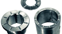
Flat-land thrust bearing surfaces are typically segmented, and an oil film separates them from the surfaces they support. The parallelism of the two surfaces theoretically prevents any oil pressure from developing in the film. That is, an oil film between two parallel bearing surfaces should not be able to support a load.
In practice, however, thermal expansion of the oil and bearing surfaces lets oil-film pressure develop to some extent. Flat-land thrust bearings will never hold more than 20 to 25% of the load supported by their tapered-land or stepped counterparts which have physical wedges to pressurize oil in the direction of sliding.
By understanding how flat-land thrust bearings work and what controls their performance characteristics such as load capacity, power loss, and temperature rise, engineers can get the most out of turbines, compressors, gear sets, and other rotating machines for light loads, simple axial positioning, and occasional reverse thrust.
Load limits
Flat-land thrust bearings depend on efficient oil delivery to the bearing surface for their thrust-load capabilities. Small flat-land bearings often lack surface features to help channel the oil. Bearings of this type, including small washers and thrust shoulders on sleeve bushings, are commonly used for loads of 20 to 35 psi.
Adding radial grooves to better distribute feed oil raises load capacity to 125 psi in larger bearings. Higher oil viscosities, faster speeds, greater oil-feed volumes, and self-lubricating bearing materials that don’t depend on oil films can all further boost load capacity.
Although these loads represent the suggested design envelope, in practice, the loads causing bearing failure commonly exceed these limits by a factor of two or more.
In addition to load capacity, engineers using flat-land thrust bearings need to predict operating characteristics like film thickness, oil-flow rate, power loss, and subsequent temperature rise.
Film thickness
The key characteristic in any thrust bearing is the thickness, or height, of the oil film between the bearing and rotating thrust runner. It is this film that actually supports the bearing load. At the oil inlet, the film is at its maximum thickness, h1. It thins out toward trailing edge to a minimum thickness, h2 that depends on surface velocity, U, and unit pressure, P.
Thrust-bearing surfaces are often tapered to enhance pumping action and pressurize the oil film for higher load capacity. But bearing surfaces without pumping wedge geometry generate no film pressure; the corresponding load capacity is nil.
In actual bearings, however, oil-film pressure is generated by two secondary effects: thermal expansion — of the passing oil and of the bearing surface as it is heated by the oil — and possible elastic deformation of the surfaces.
The following minimum-film-thickness relation describes behavior in many thrust bearings:
h2 = Kh (µ × U × B/P)0.5
where Kh = a dimensionless film thickness coefficient; μ = oil-film viscosity in reyns (lb-sec/in.2) at the mean bearing temperature; U = surface velocity at the mean diameter in in./sec (ips); B = bearing segment breadth (circumferential length at the mean diameter) in inches; and P = unit
projected load on the bearing surface in lb/in.2 P, in turn, is calculated from the load, W, in lb and the segment area, A, in in.2
P = W/A = W/(L × B)
where L = half the difference between the bearing’s outer and inner diameters in inches.
Experience with industrial and marine steam turbines shows many flat-land bearings with radial oil grooves and sectors with L/B ~ 1 have h1/h2 = 1.3 to 1.5. With this film-thickness ratio and L/B, oil-film computer simulations show the dimensionless coefficient Kh to be 0.23.
Another common flat-land thrust bearing configuration with radially narrow, elongated sectors is seen in thrust shoulders on sleeve bearings such as those for industrial electric motors. Temperature-load capacity tests show this design to have a lower h1/h2 of 1.2.
The elongated arc causes oil loss from the outside diameter, so film pressure peaks near the leading edge and minimum film thickness is reached well before the trailing edge. An equivalent L/B of 0.75 is therefore appropriate for this geometry.
A corresponding Kh of 0.15 was found to describe the behavior of thrust faces with four, six, and 12 radial oil grooves.
Oil flow
Oil typically flows between a flat bearing segment and parallel thrust runner at approximately half the runner surface speed, U. Multiply by the cross-sectional area of the flow, the film height times the segment length, to get the flow rate:
Q = 0.5 × h × U × L.
In practice, film thickness can vary. The flow rate is also affected by pressure and side flow. Use the empirically derived dimensionless flow rate coefficient, Kq, to account for these phenomena:
Q = Kq × h2 × U × L.
Power loss
Engineers may look at viscous drag resistance, F, on a stationary flat-bearing segment as a measure of efficiency. It depends on fluid viscosity, μ; surface velocity, U; and film thickness, h; with:
F = μ × U × B × L/h.
But a more useful measure is power loss, E, which is F × U. Use the dimensionless flow-friction coefficient, Kf, to reflect secondary film flow and geometric effects:
E = Kf × μ × U2 × B × L/h2.
Temperature rise
Power loss causes oil temperature to increase by ∆T:
∆T = E/(Q × ρ × Cp)
where ρ = density (0.0307 lb/in.2 for mineral oils) and Cp = specific heat (4,400 in.-lbm/(°F-lbm) for mineral oils).
Substituting for E, Q, and h2 allows engineers to drop oil viscosity from the expression, because a thicker oil film compensates for the greater viscous drag of higher viscosity oil or higher speeds.
∆T = [Kf/(K q × Kh2 × ρ × Cp)] × P
This can be further simplified by using a dimensionless temperature coefficient, Kt, so that temperature rise is proportional to unit axial load, P.
∆T = Kt × P
Values of Kt drop slightly with increased loading. That’s because a more pronounced thermal wedge shape forms in the bearing with the higher temperature.
In addition, bearings where L/B deviates significantly from unity will have smaller Kt and lower load capacity. However research shows the number of oil-distributing grooves has no significant effect on ∆T.
Boosting load capacity
Flat-land thrust bearings have inherently low load capacity. However, some modifications can help engineers improve load capacity in these bearings.
Try increasing the base viscosity of the oil. This can create a thicker oil film without increasing bearing temperature. Adding radial grooves to distribute oil over the plain thrust face can also boost film thickness, especially when oil-feed pressure is maintained.
To get even more out of thrust bearings, create more bearing area by increasing the bearing’s OD. Or turn them into the higher-load tapered or step thrust bearings by incorporating those geometries into the thrust-face sector. If machining the thrust faces isn’t possible, mounting individual flat-land segments on rubber backings or springs will let them pivot to create an oil wedge.
Application example 1 Assuming that oil grooves take up 20% of the area, the bearing area, A, is: Then the unit pressure, P, is: Radial length, L, and circumferential breadth, B, at the mean diameter for each of the 14 flat segments are: Determine the velocity, U, at the 8.5-in. mean diameter, D: Next, calculate the bearing’s temperature rise (∆T), minimum film thickness (h2), power loss (E), and oil flow (Q). Multiplying by 14 sectors gives a total oil flow of 18.3 in.3/sec. Application example 2 With six radial oil grooves, each 1/8-in. wide, the bearing area, A, is: Radial length, L, and mean circumferential breadth, B, for each of the six flat pads are: Determine the velocity, U, at the 4.5-in. mean diameter, D, of the flat pads at 3,600 rpm: Next, calculate the bearing’s performance characteristics: temperature rise (∆T), minimum film thickness (h2), power loss (E), and oil flow (Q). h2 = Kt × (µ × U × B/P)0.5 E = Kf × μ × U2 × B × L/h2 Q = Kq × h2 × U × L = 0.58 × (0.0014 in.) × (848 ips) × (0.5 in.) = 0.34 in.3/sec |
About the Author
Jessica Shapiro
Jessica serves as Associate Editor - 3 years service, M.S. Mechanical Engineering, Drexel University.
Work experience: Materials engineer, The Boeing Company; Primary editor for mechanical and fastening & joining.
Voice Your Opinion!
To join the conversation, and become an exclusive member of Machine Design, create an account today!

Leaders relevant to this article: