Authored by: |
Autofrettage is a little-known metalworking process that typically applies only to components subject to pressures above 15,000 psi pulsating at frequencies above 5 Hz. Common examples include cannon and gun barrels, liners and jackets for high-pressure pumps, and automotive common-rail injection components for cars and trucks.
In French, “frettage” means the hooping of casks or cylindrical containers to increase strength against internal pressure. “Auto” means the material itself withstands the stresses without external devices such as the above-mentioned hoops.
In the engineering world, autofrettage alters a container’s inside surface by inducing permanent compression to the material’s inner layers — even in the absence of internal pressure. The process artificially strains the material with stresses above the elastic limit, taking them just into the plastic region. It is similar to the process of prestressing concrete for building bridges.
One approach to autofrettage involves peening the surface with metallic or ceramic spheres. (Recall the famous swords of Toledo and Damascus were made by hammering, first by hot forming and then by cold working, to give them hardness and flexibility.) Another technique is based on forcibly inserting a mandrel that is larger than the hole, straining the inner material layers (and, to a smaller extent, the outer material structure.)
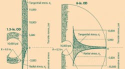
As a starting point, consider the stresses in tubes with a 1.0-in. inner diameter and 10,000-psi internal pressure. Outer diameters are 1.5, 4.0, and 6.0 in.
(As stresses are proportional to internal pressure, this round number —10,000 psi — makes it easy to determine new stresses if pressure changes. For instance, with a pressure of 14,000 psi, simply multiply the stresses by 1.4.)
Curves are drawn using the well-known relationships for tubes that have nonnegligible thickness with respect to diameter. The σZ (stress along the tube’s main axis) is considered zero, meaning the two ends are held by external supports.
From the stress curves, one can make the following observations:
• For relatively thin tubes, there is little difference between the highest and lowest stresses, and the material is more uniformly stressed.
• For thicker tubes, it’s just the opposite. There is a wide difference between the highest and lowest stresses. Inner layers handle most of the load while the outer ones do little work. Such designs, therefore, waste a large amount of material and unnecessarily increase cost, weight, and size. Comparing tubes with outer diameters of 1.5 and 6 in., the highest tangential stress on the inner surface of the larger tube decreases about 50%, but material mass increases about 2,800%!
• Inner and outer radial stresses are the same for all tubes. (It is also intuitive: the inner one is same as pressure, the outer one is always zero.) And they are compression stresses — pressure pushes inner layers against the outer layers.
• The tangential stress is tensile. Therefore, material grains in the same layer try to move away from one another, encouraging the formation of cracks from inside to outside. Such cracks propagate quickly if pressure is pulsing.
Under static pressure high stresses may be tolerated, provided engineers apply an appropriate safety factor. But if pressure swings between high and low values at frequencies higher than 5 Hz, the material is stressed such that fatigue becomes a dangerous concern. Autofrettage helps alleviate the problem.
As an example of how autofrettage reduces internal stresses, consider a tube of AISI 316L austenitic stainless steel. A strain-stress curve of this steel shows that the region of normal use (strain <1%) has an upper limit of allowable stress of about 40,000 psi. And if the tube is part of a pump (for instance: valves, liners, or seal seats) or the barrel of a rapid-fire gun, it is not uncommon to have pressure pulsating at approximately 10 Hz.
In this dynamic case, for a reasonable life (109 cycles) allowable stress should be about half that for static conditions, or 20,000 psi. And with an appropriate safety factor, it is advisable not to exceed a stress of 14,000 psi.
With such limitations, a conventional tube must have an outer diameter about 4.0 in. for 10,000 psi of inner pressure. (See the stress-analysis in the accompanying “Without autofrettage” graphic under the heading, Effects of autofrettage.) The OD will be even larger at higher pressures with an absurd waste of material, as mentioned above.
Thus, there is great interest in alternatives such as autofrettage. The second graphic, “With autofrettage,” shows the stress analysis of an equivalent tube postprocessed by auto-frettage, with and without internal pressure.
Here are some interesting observations concerning the autofrettage tube, as it compares to the untreated tube:
• With no internal pressure (rest conditions), autofrettage highly compresses the tube’s inner surface, with residual stress at about the yield limit.
• Subjected to pressure, the dangerous σT spike (that without autofrettage is just on the inner surface of the tube, possibly triggering a crack) is now well into the thickness, and therefore less harmful than at the inner surface. σT becomes a compression stress instead of a tensile stress and, therefore, compacts the material fibers without cracking the wall.
• The outer layers, which contribute little to the tube’s structural integrity without autofrettage, now substantially help withstand the stresses.
• It moves the point of maximum radial stress σR away from the tube’s interior surface, making more-rational use of the material.
Estimates are that autofrettage postprocessing increases the ability to withstand pulsating pressure spikes by a factor of 1.8 in tubes with substantial thicknesses. This gives engineers the leeway to reduce thickness without sacrificing performance.
About the Author
Kenneth Korane
Ken Korane holds a B.S. Mechanical Engineering from The Ohio State University. In addition to serving as an editor at Machine Design until August 2015, his prior work experience includes product engineer at Parker Hannifin Corp. and mechanical design engineer at Euclid Inc.
Voice Your Opinion!
To join the conversation, and become an exclusive member of Machine Design, create an account today!

Leaders relevant to this article: