The difference between robotic grippers with parallel, three-finger, and angled designs
Identifying the best gripper for the application can be a daunting task given the thousands of different combinations, part numbers, and variation in gripper names. Yet there are only three basic types of grippers. Knowing the fundamentals of each can help engineers narrow their choices and speed the design process.
Paging through a gripper supplier's parts catalog or searching for parts on the Internet can lead a design engineer to an overwhelming selection of components. To find the right gripper for the application as quickly and accurately as possible, this article provides some helpful tips.
Start with the basics
The majority of grippers are variations of three fundamental designs: Parallel, three-finger, and angled grippers.
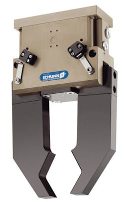
Parallel grippers are just what their name implies — two slides either closing parallel to the workpiece to grip its outside edges, or opening out to put pressure on inside walls. Parallel grippers are by far the most commonly applied design.
Three-finger grippers are used to center the workpiece between the fingers, which are offset by 120° ... and the three fingers slide the workpiece to the gripper's center, holding the object snugly.
Another option is angled grippers, which approach the sides of the workpiece from various angles, for example, 30°, 40°, or 80° — visualize mechanical fingers coming out at an angle to hold a basketball. Many standard angled grippers can be adjusted to various angles according to the workpiece. Angled grippers are suitable for holding larger workpieces and those with odd shapes. They're also used where space is too tight for a parallel gripper to open wide enough to hold the workpiece. A variation of the angled gripper is the radial gripper: The fingers open a full 180° — useful where vertical space is limited. Fully open radial fingers can rest just above or below the workpiece and close when it is in position.
Parallel, three-finger, and angled grippers come in a host of sizes for varying degrees of gripping force, which can range from 20 N to more than 6,300 N for high-force models. Closing times can vary from 0.1 to less than 0.001 sec for standard parts with repetition accuracy an average of ± 0.01 to ± 0.05 mm. What's more, suppliers often work with design engineers on custom solutions not accommodated by standard parts.
Specialty gripper variations
Beyond the traditional parallel, three-finger, and angular types, other styles of grippers exist. For example, bellows grippers are used for internal gripping on the inside walls of fragile workpieces, such as bottles or jugs. The flexible bellows expand, pressing against the workpiece.
A new generation of adaptive grippers is also being developed, such as one gripper based on the mechanics of a fish fin. This robotic gripper's fingers effectively wrap around and adapt to different shapes with flexibility up to 360°. The end effector has good range of motion and may not need to be changed when different products come down the line. That said, these specialized grippers have fairly limited applications compared to the traditional gripper designs.
But what powers them?
Pneumatic versus electric designs
All three of the basic gripper styles are available in either pneumatic or electric versions. Pneumatic grippers are generally less expensive upfront, simpler, lighter, and offer higher gripping forces than electric versions, but electric grippers are somewhat less expensive to operate than their pneumatic counterparts. Even so, today's pneumatic systems offer diagnostic features that help maintenance personnel and machine operators identify air pressure loss, which contributes to higher energy costs in pneumatic systems.
The motion-design process starts with defining the shape and size of the workpiece plus the available space, and then works up through the gripper and the rest of the mechanical assembly. For example, a lighter gripper requires a lighter handling system, while a heavier gripper requires heftier machine parts to support it.
A cost/benefit analysis can help determine whether a pneumatic or electric device is more advantageous over the machine's lifecycle.
Grip upon opening, or upon closing
Pneumatic grippers are typically designed as double action — either air open or air closed. Variations include springs to ensure that the workpiece remains gripped should air flow stop. Grippers can also come in sealed configurations suitable for harsh conditions, such as protection against drilling emulsion or dust.
Other options include long-stroke grippers with strokes from 20 to 150 mm; for long centering strokes, electric grippers are available with strokes to 1.5 m. Sensing and feedback options abound as well. In short, a host of gripping solutions exists for everything from baked goods to automotive parts.
The three basic designs — parallel, three-finger, and angled grippers — accommodate most workpiece sizes, available machine space, torque and repetition requirements, and environmental constraints. For more information, contact Festo at (800) 993-3786.
EXAMPLE APPLICATION:
Robotic layer-picking offers gripping alternative
Today's beverage suppliers need to be as automated and centralized as possible in order to offer competitive prices and streamlined retail distribution. Much of this efficiency can be gained by automating tasks such as palletizing and layer picking. Case in point: KUKA Systems Corp. North America, Sterling Heights, Mich., recently designed and installed an integrated pallet-building line for a major beverage company. The result? The newly automated line offers a major increase in throughput over manual operations traditionally conducted by forklift operators moving pallets around warehouses.

The KUKA Systems layer palletizing and case-picking line is now in use, helping reduce overall supply chain costs. Such a setup lets the soft drink maker move completed order pallets from a large regional distribution center directly to major retail outlets, shortening the distribution pathway. Previously, these pallets had been assembled manually at small local warehouses, which was both time and labor intensive.
The newly deployed system can process 5,000 cases per hour. It features KUKA's automated layer-picking system, as well as its layer-forming and mixed palletizing cell. Handling of the highest demand products is fully automated: This particular cell features an advanced layer-pick head on a robot arm that lifts cases from underneath, reducing the risk of product damage associated with traditional grippers that use clamps or vacuum technology to grab cases from the top or sides.
By combining layer-picking and mixed layer-building technology with order sequencing logic, the system handles peak volume while strategically building and staging pallets for loading onto trucks and delivery to stores.
ANOTHER ENGINEER'S INPUT:
Gripper terminology and another way to pick a gripper
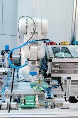
Grippers vary from simple configurations such as two-jaw parallel designs to complex, handlike structures with advanced sensors, control units, and servomotors. To learn more about gripping technology, we turned to Jesse Hayes, automation group manager at Schunk Inc., Morrisville, N.C.
Hayes explains that the two-jaw parallel gripper is the most versatile design and is able to handle a large percentage of applications.
“The reason why the two-jaw parallel design is the most commonly used is because it can handle so many part shapes and sizes. It can also do the same job as the other two basic gripper types, the three-jaw gripper and the two-jaw angular,” says Hayes.

For example, the two-jaw parallel gripper can grip both round and square parts either radially (from the side) or axially (from the top). In contrast, a three-jaw concentric gripper can only handle round parts axially, like gripping a coffee cup from the top around its rim, or from the inside, pushing against its inner diameter.
That's not to say the three-jaw concentric design isn't useful. In fact, this gripper type is used in 20% to 30% of all applications. The next most common style — used in 10% to 20% of applications — is the two-jaw angular gripper. This design is best suited to grip round parts from the side, like using your thumb and index finger to pick up a coffee cup or other round object.
Beyond these three basic gripper modules that come in a range of sizes and configurations are specialty styles, such as vacuum grippers that employ suction and adhesive grippers that use sticky materials to move parts and then let go. Hayes explains that most grippers are designed for one specific part, and perform a simple pick-up-and-release operation.
Regarding terminology, the words “jaw” and “finger” are sometimes used interchangeably, as a kind of industry slang. However, Hayes explains that it is actually a gripper's jaw that supports and handles the bearing loads; the finger is a customized piece (made for a specific product) that an end-user bolts on to the jaw.
“Most customers design and machine their own fingers to bolt onto our gripper jaws. But if they need help with finger design and manufacturing, we can do that as well,” says Hayes.
As far as the gripper design itself, this can vary substantially based on part size and shape. The smaller the part, the more likely it is to be handled in higher volume, which requires fast-actuating designs for use in assembly as well as pick and place applications. Small parts generally refer to those weighing 5 lb or less. For larger parts (those that weigh 5 to 30 or 40 lb), grippers within the same product family can be up or downsized. Larger parts are generally found in material handling applications, such as moving parts on and off of conveyors or loading raw material into machine tools and removing finished parts.
Regarding gripper actuation, about 80% of today's grippers are pneumatic. The reason? Grippers are mostly short-stroke components, so they don't consume a lot of air, according to Hayes. “Think about a long-stroke linear actuator,” Hayes says. “This component uses a lot of compressed air along its stroke length, so more of these designs are becoming electric. One day, we may see more servo-electric grippers in use, but today they're roughly two or three times as expensive as pneumatic designs.”
Bridging the divide between pneumatic and servo-electric grippers are pneumatic designs that use advanced sensors to measure the gripping force on the part, adjusting to a softer or firmer grip as necessary to the application. Hydraulic grippers are also available. “Some engineers believe that hydraulic designs provide a higher gripping force than pneumatic types, but that's not true,” explains Hayes. “The only reason to use a hydraulic gripper is if the piece of equipment it's going on is entirely hydraulic. That way, no new air lines need to be installed.”
Servo-electric gripping hands are also under development. Their ultimate benefit: Flexibility. Most modern assembly lines strive to be as flexible as possible, to be able to accommodate packaging changes and product changes, particularly in the consumer goods industry. Typical pneumatic grippers are rigid — designed specifically for one product. When a new product shape comes out or packaging is redesigned, new fingers must be machined and swapped out in place of old ones. With consumer goods changing their looks every two or three quarters, this can become expensive and time-consuming, says Hayes.
In contrast to these traditional rigid designs are gripping hands that can hold objects in any orientation. “Today's hands are expensive, costing around $80,000 compared to typical pneumatic grippers that cost an average of $300 to $1,000,” says Hayes. “However, prices are expected to decrease substantially over the next three to five years as manufacturers learn which features are the most useful and trim the nonessential ones.”
What's more, the use of flexible hands that can work with many different products will reduce the need for new fixturing and tooling, which is required today to present parts to grippers in a certain orientation. Instead, hands can be configured to pick up different parts in any orientation. To do this, a typical gripping hand is built like a miniature robot, complete with seven servomotors (for seven DOF), a control unit for each motor, and several advanced sensors. “When an end-user can save $30,000 worth of new fixturing and tooling by using a robotic hand that costs around $8,000, that's when we'll see these in more widespread use,” notes Hayes. For more information, contact Schunk at (800) 772-4865.
FINAL BIT OF GRIPPER-RELATED NEWS:
New robot safety standard debuts
Did you know that a new robot safety standard is in the pipeline for North America? Much of the work on harmonizing North American standards with those of ISO is already published in the Robotic Industries Association (RIA) Draft Standard R15.06-201X Robots and Robotic Devices — Safety Requirements, which clarifies what's in store for the industry.
“This (publication of ISO 10218) means the basic technical requirements are now set for the revised R15.06,” says Jeff Fryman, RIA's director of standards development. “Since the ISO standard only looks forward from the date of publication, the issues to be resolved by the R15.06 drafting committee have to do with any guidance for existing robots and robot systems, particularly those that do not meet the technical requirements of the standard's 1999 edition. Unique requirements for the U.S., mostly directed to the end user, must be added, and the annexes updated.”
The ANSI/RIA R15.06 National Robot Safety Standard enables worldwide compliance from one document on robot safety, and also provides new risk-assessment guidance.
Voice Your Opinion!
To join the conversation, and become an exclusive member of Machine Design, create an account today!

Leaders relevant to this article: