Photoelectric sensors meet new challenges
Background suppression, sharp cutoff, polarization, and transparent object detection are all examples of new technologies that give photoelectric sensors the ability to solve challenging sensing applications.
Before examining these technologies and their applications, it’s important to understand a concept called operating margin, otherwise known as excess gain, because it plays a key role in these solutions. Operating margin is the ratio of the electrical signal (usually voltage) available to the minimum signal required to trigger the amplifier and output of a sensing device. For example, a margin of one means that the sensor is on its threshold of operation. Conversely, a margin of 20 or more enables the same sensor to “see” many objects, even those with a flat black finish.
No photoelectric sensor should be applied in an industrial setting at an operating margin of one. In such situations, small changes in the environment, such as airborne dust or dirt accumulating on the lens, can impair operation of the device. Hence, it is advisable to install photoelectric sensors where they can maintain an operating margin of at least two.
Margin is usually described graphically. When operating margin is plotted against distance, the result is a traditional bell curve. Because of different design objectives, each sensor exhibits its own curve. Be aware, however, that gain can be adjusted by a “sensitivity” knob on a photosensing device. Decreasing gain from its maximum setting causes a loss of operating margin.
Background suppression
In the past, a common dilemma in photoelectric sensing was the need to detect an object against a nearby or more reflective background. Interference caused by that background often made the use of a conventional diffuse sensor ineffective. But, the advent of a special type of diffuse sensor now makes this problem easy to solve.
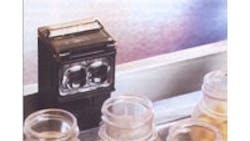
This device, a background suppression sensor, is different than other types in that it has two photodetectors in one housing. One photodetector senses objects while the other “looks” straight ahead, sensing background, Figure 1.
The sensor receives a signal from the photodetector looking at an object and subtracts its value from the signal received from the background photodetector. The background value is thereby eliminated, and the remaining signal is then amplified.
The distance at which a background signal is suppressed is adjustable, and this adjustment replaces the traditional gain setting on a standard diffuse sensor. The user, in effect, creates a different margin curve for each distance setting. With this adjustment, a background suppression device is generally effective from a sensing distance of zero to the maximum sensing distance set on the device.
For example, with the device set at 8 in., Figure 2, a white background at 8 in. or more is ignored, while a black object can be detected at a distance of 7.7 in. or less. This is a difficult sensing scenario because a white background is highly reflective, whereas a black object is highly light absorbent.
A background suppression device can also solve a number of other difficult sensing problems. For example, magazines moving on a belt conveyor can be detected by such a device looking straight down from above. Even if the background conveyor belt is bright white, the sensor still functions as well as if the belt was black.
Continue on Page2
Sharp cutoff
There are other situations where the distance between the background and the object being sensed is several inches or more, or where access to the other side of the object is impossible, ruling out the use of a retroreflective or transmitted beam sensor. Examples include a very narrow conveyor or a conveyor behind which personnel are moving. In such cases, the solution may be a sharp cutoff sensor.
With a sharp cutoff device, a margin of 20 or more is sustained from 0.5 to 2 in. sensing distance. Objects within this range can usually be sensed regardless of their color or texture. Within a wider range, 0.1 to 3 in., the device can sense more reflective objects.
However, beyond the 3 in. boundary, the margin falls below one. Thus, this particular device only senses objects within a precise range of distance, that is between 0.1 and 3 in.
Sharp cutoff sensors can operate in areas where space is limited. For example, if beverage cans are traveling in opposite directions on two 4-in.-wide parallel conveyors spaced only 1-in. apart, a sharp cutoff sensor can be set up to detect the cans moving on one conveyor while ignoring the movement of cans on the adjacent conveyor. Similarly, if objects are traveling on a conveyor and factory workers need to walk alongside the conveyor, a sharp cutoff sensor can detect the objects while ignoring the personnel movements.
Polarization
The last two photosensing technologies are quite different than the first two in terms of how they work and what tasks they perform.
For example, the dependable sensing of shiny objects was once considered almost impossible with self-contained photoelectric sensors. Items such as tin cans, clear plastic bottles, waxed packaging, glass bottles, and products wrapped in cellophane or foil are notorious for giving off reflections that tricked photoelectric sensors. Such objects can fool a retroreflective sensor’s beam because, at a 90- deg angle of incidence, the object can act precisely like a reflector.
One common solution, the transmitted beam sensor, works well, but the space and cost required for two units (see box) may sometimes be restrictive. The solution for sensing tin cans and bottles filled with product was to position a traditional retroreflective sensor at an angle, thereby eliminating the troublesome 90-deg angle of incidence between reflective object and sensor. However, problems still remained in the following areas:
• Vibration in transporting bottles and cans, making angling undependable.
• Detecting other reflective objects such as shrink wrap, foil, or irregularly shaped glass where angling doesn’t work because the objects scatter reflective light.
The solution to sensing in these scenarios is to add polarized filters. Like the retroreflective device, a single unit holds an emitter and a photodetector, which is placed opposite a reflector.
With a polarized sensor, two 90-deg displaced polarized filters are placed in front of the emitter and photodetector. Nonpolarized light is emitted from the LED, polarized by the filter, then projected through a lens toward the reflective target. The emitted light hits the reflector and is depolarized. That portion of the returning depolarized light that is 90 deg out of phase is allowed to pass through the second filter, illuminating the photodetector, Figure 3.
Here, the main concern is with sensing shiny objects that are at a right angle to the light beam (objects with other angles are of no concern because they reflect light away from the sensor). When a shiny object at a right angle breaks the beam, the angle of incidence equals the angle of the reflection and the light, still polarized, is reflected back to the photosensor. However, the sensor can’t be tricked. This light will not pass through the filter because it is not out of phase (depolarized). The photodetector is no longer illuminated, and the sensor is tripped. In this way, polarized sensors are able to ignore reflected light 100 times brighter than a nonpolarized sensor.
Continue on Page 3
However, polarized sensors do have a limitation. They may not be dependable beyond the first surface of a clear object. The reason is that light can be depolarized when, for example, the middle of a plastic bottle passes through the sensor’s beam. The second surface of the bottle can depolarize returning light, incorrectly telling the sensor that nothing is there. Only the leading or trailing edge of a clear bottle, where the curvature of the plastic reaches its highest angle, is useful for tripping the sensor.
Transparent object detection
Detecting transparent objects, such as clear plastic bottles or glass containers, presents another challenge to photoelectric sensing because these objects absorb very little light. To meet this challenge, a special type of polarized sensor, called a transparent object detector, has been developed. This device uses a close-differential amplifier to sense the presence of a clear object. This amplifier enables transparent object detectors to operate with the small changes in light absorption that are exhibited by objects such as clear plastic bottles.
Brushing up on photoelectric basicsIn its most basic form, a photoelectric sensor is a switch-like device in which the mechanical actuator or lever arm function is replaced by a beam of light. This light beam, generated by a light emitting diode (LED), can be used to detect objects at distances from less than 1 in. to several hundred feet. Photoelectric sensors operate by sensing a change in the amount of light received by the photodetector. The change in light could be caused by the presence or absence of an object, its size, shape, reflectivity, or color. There are three basic types of photoelectric sensors: transmitted beam (also known as through-beam), retroreflective, and diffuse. In the transmitted beam type, the light source (LED) and the receiver are positioned opposite each other so that emitted light shines on the receiver. The sensor changes state when an object breaks the beam. A retroreflective sensor contains the light emitter and photodetector in a single unit, along with a signal amplifier. A light beam is projected from the sensor to a retroreflective target and back to the sensor. An object is sensed when it interrupts the light beam. Because of the ease of installation, alignment, and relatively low cost, the retroreflective sensor is the most popular. Finally, like retroreflective types, diffuse sensors also contain a light emitter, photodetector, and amplifier in a single unit. However, in this case, the object to be sensed must serve as the reflector. Light emitted from the sensor strikes the object to be sensed and is scattered in many directions — a small portion of it returning to the photosensor. The device then changes state. |
Fred Poppe is the area manager for the Presence Sensing Div. of Allen-Bradley Co. Inc., Chicago.
Related Articles
Product Spotlight: Proximity Sensors
Color sorting quick facts
About the Author
Voice Your Opinion!
To join the conversation, and become an exclusive member of Machine Design, create an account today!

Leaders relevant to this article: